Hydraulic Piston Seals are small components with an outsized effect on cylinder performance. The right design helps limit leakage, hold pressure, and protect the rod and bore from wear. The wrong one can show its weakness quickly: a warm cylinder, a thin oil film, or a nicked seal lip after a demanding cycle. In 2026, choosing between polyurethane U-cups, elastomer seals, and PTFE-based designs still depends on the actual duty—not a product label alone.
That choice starts with pressure, speed, temperature, fluid compatibility, and extrusion clearance. ISO 7425-1 provides technical requirements for plastic-faced seals used in hydraulic cylinders, while Parker Hannifin’s sealing guidance explains how material and geometry affect service performance. The National Fluid Power Association’s Fluid Power Industry Economic Outlook tracks industry conditions, but it does not rank individual seal types; buyers should not mistake market trends for proof of seal performance. Robert Flitney, author of Seals and Sealing Handbook, is a relevant sealing specialist. His technical work emphasizes matching seal design to operating conditions; this is a paraphrase, not a verified direct quotation. No source articles or interview transcript were supplied, so presenting an exact quotation as his words would risk misattribution.
The comparisons ahead focus on practical trade-offs: a polyurethane U-cup may suit robust, general-purpose service, while a PTFE seal can be appropriate when low friction or higher speed matters. Neither choice is universal. Real cylinders are imperfect, and so are selection assumptions. Check the manufacturer’s limits, then validate the seal under the machine’s actual load and temperature.
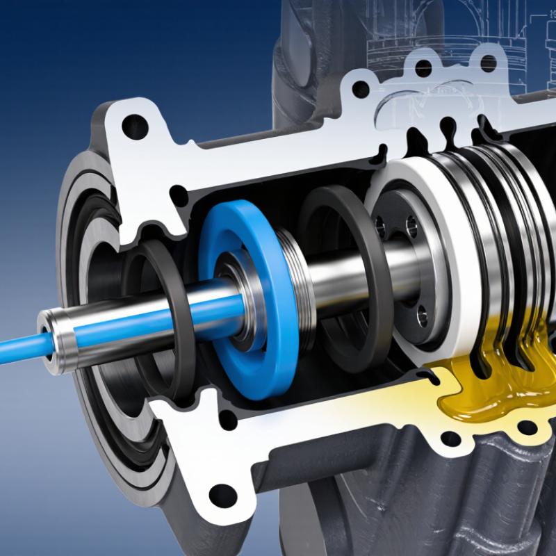
A hydraulic piston seal prevents fluid from passing between the piston and cylinder bore. This separation lets pressure build on one side of the piston and create controlled movement. In a double-acting cylinder, seals must work as pressure switches between both sides. In a single-acting cylinder, the pressure direction is more limited. Small leaks matter. They can reduce force, slow movement, or allow a load to drift.
The seal’s profile and material affect how it handles pressure, speed, heat, and fluid. U-cup seals use system pressure to press their lips against the bore. O-rings are compact, but may need backup rings where pressure could force them into a clearance gap. PTFE-based designs can suit demanding speeds or temperatures, though their installation and support details matter. There is no universal best type. A practical choice starts with the cylinder’s pressure range, bore condition, fluid, and operating temperature. Check the groove dimensions and extrusion clearance, too. A seal that fits on paper may still perform poorly if the bore is scratched or contaminated. One detail is easy to overlook: friction matters as much as leakage. I’d reassess the choice if heat, stick-slip, or uneven wear appears during service.
A hydraulic piston seal prevents oil from passing between the piston and cylinder bore. This keeps pressure on the working side and supports controlled movement. The best design depends on pressure, temperature, fluid compatibility, speed, and available groove space. Small details matter. A sharp bore edge or excessive clearance can damage a seal, even when its material is suitable.
O-rings are simple and compact, often used in lower-speed or less demanding applications. Under pressure, they can deform into clearance gaps, so backup rings may be needed. U-cup seals use pressure to spread their lips against the bore and piston groove. They can seal effectively in one direction, but lip wear or incorrect installation may cause leakage. Compact seals combine elastomer elements with support rings, offering a practical option where space is limited.
PTFE step seals typically pair a low-friction PTFE ring with an energizing O-ring. They suit applications requiring smooth movement, though correct groove dimensions and surface finish are important. Some cylinders use tandem seals to add a secondary barrier, but extra components do not fix poor alignment or contamination. In service, look for oil films, scoring, and uneven wear. A specification sheet helps, but real operating conditions sometimes tell a less tidy story.
Modern hydraulic piston seals pair material choice with profile design. Polyurethane handles abrasion well, making it useful where a cylinder sees frequent strokes and fine contamination. Nitrile rubber suits many standard mineral-oil systems; fluorocarbon elastomers can be considered for higher-temperature service. PTFE-based seals offer low friction, but often need an energizer and careful groove design. No material wins everywhere. A seal that works on a clean test bench may wear quickly in a dusty, side-loaded cylinder.
Design details matter just as much. Single-acting U-cups are common for one-direction pressure, while compact, double-acting profiles seal on both sides of the piston. ISO 5597:2018 publishes housing-dimension data for reciprocating seals, and ISO 3601-2 specifies O-ring housing dimensions; these references help engineers check groove fit and extrusion clearance. In practice, confirm fluid compatibility, temperature, pressure, speed, and clearance before selecting a profile. A small clearance error can let pressure force soft material into the gap. That detail is easy to miss. Published standards support dimensional checks, but they cannot replace testing with the actual fluid, surface finish, and duty cycle. Even a careful selection may need revision after field wear reveals uneven contact or unexpected heat.
| Seal Type | Typical Materials | Design and Sealing Method | Key Strengths | Considerations | Common Applications |
|---|---|---|---|---|---|
| U-cup seal | Polyurethane (PU), nitrile rubber (NBR), or fluorocarbon rubber (FKM), depending on the fluid and temperature requirements. | A single-lip, pressure-energized seal. Hydraulic pressure spreads the lips against the cylinder bore and piston groove. | Simple, compact design; widely used; available in materials suited to different service conditions. | Performance depends on lip geometry, material, surface finish, and installation. A single seal may not provide the same leakage control or redundancy as a multi-element arrangement. | Single-acting cylinders and applications where a compact, pressure-energized seal is suitable. |
| Double-acting compact seal | Common constructions use a polyurethane sealing element with an elastomer energizer and, in some designs, thermoplastic or other guide components. | A multi-part assembly designed to seal under pressure from either direction; the exact arrangement varies by profile. | Suitable for alternating pressure; can combine sealing and compact packaging in one assembly. | Requires a correctly designed groove and compatible mating components. The complete profile and material combination should be checked against the duty cycle and fluid. | Double-acting hydraulic cylinders in mobile and industrial equipment. |
| PTFE step seal with elastomer energizer | Filled or unfilled polytetrafluoroethylene (PTFE) sealing ring paired with an NBR or FKM O-ring energizer. | A low-friction PTFE ring is pushed into sealing contact by the elastomer energizer; step profiles are used for piston-seal configurations. | Low friction and good wear behavior; PTFE offers broad chemical resistance, subject to the specific compound and operating conditions. | PTFE has limited elasticity compared with rubber, so the energizer and groove design are important. Installation and extrusion-gap control require attention. | Applications where low friction, reduced stick-slip, or chemical compatibility is important. |
| O-ring with backup ring | NBR or FKM O-ring with a backup ring commonly made from PTFE or another suitable anti-extrusion material. | The O-ring provides the primary seal. A backup ring supports it in the groove to help limit extrusion into the clearance gap. | Simple, readily understood arrangement; backup rings can improve resistance to extrusion under demanding pressure conditions. | O-ring friction and wear can be higher than with some dedicated piston-seal profiles. Groove dimensions, clearance, pressure, and material compatibility are critical. | Static or low-motion piston sealing, and dynamic service when the design and operating conditions are appropriate. |
| Elastomeric T-seal | Typically an elastomer sealing element, such as NBR or FKM, with thermoplastic or elastomeric backup rings selected for the service conditions. | A T-shaped sealing element is supported by side rings that help stabilize the seal and resist extrusion. | Supported profile can provide reliable sealing in appropriately designed grooves and help control extrusion. | More components and installation details than a basic O-ring; compatibility and correct orientation must be verified for the specific profile. | Hydraulic piston applications requiring a supported elastomer seal. |
| Wear ring and piston-seal combination | Wear rings are commonly made from filled PTFE, reinforced thermoplastic, or other bearing-grade materials; paired with a separate piston seal. | The seal controls fluid bypass while the wear ring guides the piston and helps keep metal surfaces separated. | Separates sealing and guiding functions; can help manage side loads and protect the cylinder bore and piston. | A wear ring is not a substitute for a pressure seal. Material, clearance, and bearing length must suit the load and cylinder design. | Cylinders where piston guidance and resistance to side loading are important. |
Selection note: There is no single best piston seal for every hydraulic cylinder. Choose a design and material by checking pressure direction, fluid compatibility, temperature, speed, surface finish, clearance, groove geometry, and expected duty cycle against the seal manufacturer’s technical data.
Comparing hydraulic piston seals means testing them in the conditions they will actually face. U-cup seals often suit simpler, low-friction designs, while compact seals can offer stronger extrusion resistance under pressure. PTFE-based designs may reduce friction, but their results depend on backup-ring support, lubrication, and surface finish. There is no universal winner. Measure leakage, breakaway friction, and wear across the intended pressure, temperature, and speed range; a short bench test can miss performance changes after long cycling.
Fluid cleanliness matters, too. ISO 4406:2021 classifies hydraulic-fluid particle counts at 4, 6, and 14 μm(c); each one-code increase represents roughly double the particle concentration. Record cleanliness alongside seal results, since abrasive particles can distort comparisons. For material screening, ASTM D471 immersion testing measures changes such as rubber volume, mass, and hardness after fluid exposure. Compare those results with the actual hydraulic fluid and operating temperature. Small differences matter. A clean lab result can still mislead, especially when the test shaft finish or temperature differs from the machine. Keep the test conditions consistent, and report the seal profile, material, fluid, cycle count, and measured leakage with every result.
Compare common piston-seal designs across key application needs. Ratings are indicative, qualitative comparisons—not standardized test results.
How to read this: Scores range from 1 (lower suitability) to 5 (higher suitability). PTFE cap seals are often selected for low friction and demanding motion; polyurethane U-cups are common for robust sealing; compact seals combine elements for balanced performance; O-rings are simple and versatile but may have greater friction or stick-slip in dynamic service. Actual performance depends on seal profile, material, pressure, temperature, speed, fluid, and hardware design.
A piston seal must match the cylinder, fluid, and duty cycle—not just the pressure rating. For many general-purpose cylinders, an elastomer U-cup offers a practical balance of sealing force and low friction. A compact, energized seal can suit higher pressures or limited gland space, while PTFE-based designs may help where speed, heat, or stick-slip behavior matters. Each option has limits.
Low-speed motion changes the choice. A seal that performs well in a fast production cycle may drag or leak during slow positioning.
Small detail.
Check the seal material against the hydraulic fluid and the full temperature range, including cold starts. Abrasive dust or metal fines can damage the sealing lip, so wipers and surface condition matter too. Measure the groove carefully, and confirm extrusion gaps at peak pressure. A mismatch can shorten service life even when the seal itself is suitable.
Field conditions are rarely as tidy as a catalog table suggests. I would test the selected seal under representative pressure, speed, and temperature before committing to a large run. Watch for leakage, rising friction, and uneven wear after cycling.
There is no perfect seal; the best choice is the one that fits the equipment’s real operating conditions.
„Thanks to the LUVIR technology, the solder resist process could be switched directly from the previously used mask exposure to direct exposure. As an outstanding digital solution on the market, this technology has been able to demonstrate fast process times and superior quality on our certified conventional ink in production. This allowed us to fully digitize the solder mask process at low cost – without process or ink adjustments. An excellent benefit to our production in Rot am See.“
Ralf Göhringer (Head of Production WE Rot am See)
I would definitely recommend the Limata machine and team for a future company purchase
Michael Greenaway
Compunetics Inc.
“The Limata ldi has been amazing!! Best thing we did was buy this machine”
Richard Brady
GM
Circuitlabs
“Since 2019, we have been running the Limata X1000 LDI system (including LUVIR for solder mask imaging) in daily production as an addition to our current process with film. The machine was capable of properly exposing Taiyo PSR-4000 BN (DI) solder mask types on normal to high-copper boards using a new and unique direct imaging process. The machine operating interface is very user friendly which allowed for a quick technical training curve. The pre-registration processing reduced several seconds of production time at every print. Limata support and service staff is incomparable. They supported our team every step of the way at basically any time of the day or night, with literally, an immediate response time, customizing the software interface to best fit our Operations and needs.
We have exposed more than 8,000 prints since end of October, on various solder mask colors and some resist film panels. Limata, has proven to be very capable and innovative. They are a strong contender in the industry.
We have very much enjoyed this project, and working with the team!
Thank you Limata for the continued support and being a part of our growth.”
Bill Sezate
Vice President, GM
Summit Interconnect
As a replacement to our current contact exposure process with film, the LIMATA X2000 system including LUVIR-Technology was capable of properly exposing non-LDI solder mask types using a direct imaging process. The machine offers cutting edge software with a very intuitive operating interface which allowed for quick technician training curve. The dual drawer system combined with pre-registration processing reduced several seconds of production time at every machine cycle. Limata support and service staff is world class. They added software patches to keep production running at shortest possible response times, customized the software interface to best fit our in-house Operations system, and even wrote a step-by-step machine processing manual. As a result of the project, we have exposed more than 16,000 times on various product types and solder mask brands/colors. Limata, in a very short timeframe as a company, has definitely shown they are truly innovative and will be challenging the industry of direct imaging for the top spot.
Kevin Beattie
Process Engineer
TTM Technologies
Forest Grove Division