Centrifugal Fans move air by changing its direction and increasing its pressure. Unlike axial fans, they draw air into a rotating impeller and discharge it outward. That simple path supports ventilation, cooling, dust collection, and process-air systems. Picture a wheel spinning inside a metal housing. Air enters near the center, gains velocity between curved blades, and leaves through the outlet. The casing then helps convert part of that velocity into useful static pressure.
The working principle depends on the impeller, motor, inlet, outlet, and scroll-shaped housing. As the motor turns the impeller, centrifugal force pushes air toward the blade tips. Pressure rises as the air moves through the housing and slows. Engineers assess airflow, static pressure, fan speed, power, noise, and efficiency together. A fan may deliver impressive airflow in an open test, yet perform poorly against dirty filters or long ducts. Real installations are less forgiving.
Selecting the right fan requires measured system resistance, not guesswork. Technicians should check the performance curve, operating temperature, materials, rotation direction, and maintenance access. Bearings, belts, and blades need regular inspection, especially where dust accumulates. Small alignment errors can create vibration, heat, and premature wear. This guide explains the fundamentals clearly, while recognizing a practical limitation: fan behavior changes with system design and operating conditions. Manufacturer data and qualified engineering review remain essential for critical equipment. Understanding the basics makes troubleshooting more disciplined and everyday decisions safer.
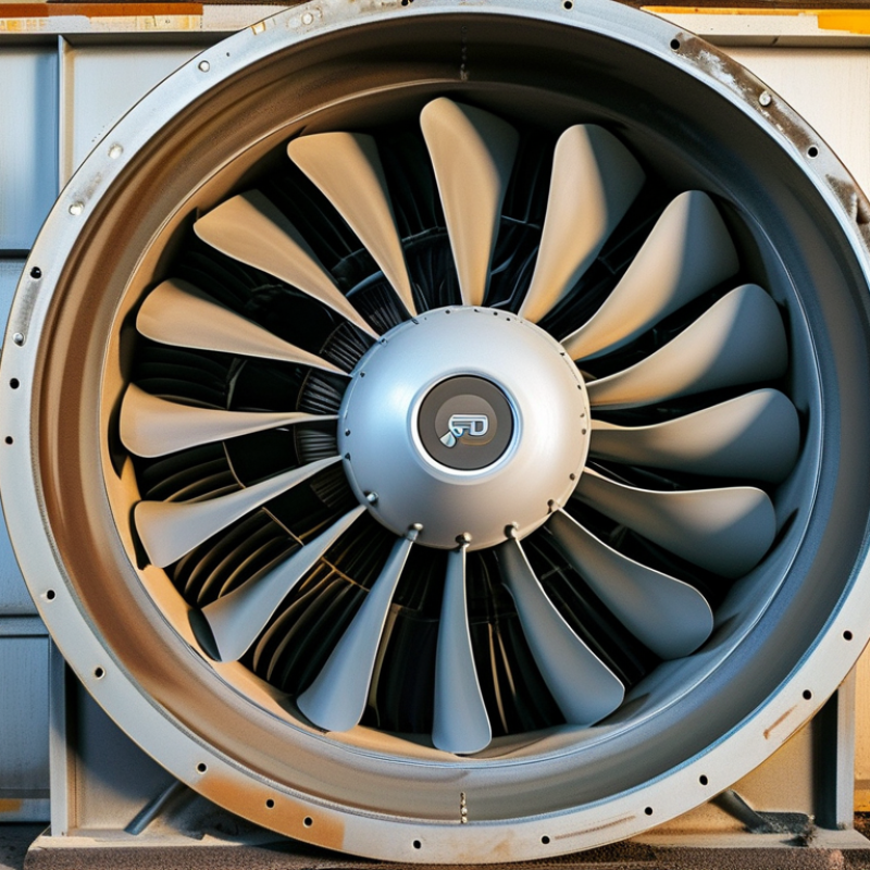
A centrifugal fan is a mechanical device that moves air by changing its direction. Air enters near the center of a rotating impeller. The blades then push it outward through centrifugal force. A surrounding housing collects this air and guides it toward the discharge opening. Unlike an axial fan, which moves air mostly in a straight line, a centrifugal fan turns the airflow across the impeller.
The main parts include the impeller, motor, shaft, housing, inlet, and outlet. Blade shape affects pressure, airflow, noise, and energy use. A narrow, high-speed wheel may create strong pressure for duct systems. A wider wheel may move more air at lower resistance. In practical inspections, dust often gathers on the blades and weakens performance. A small vibration can also indicate imbalance, loose mounting, or bearing wear. It should not be ignored.
Centrifugal fans serve ventilation, cooling, air cleaning, and process equipment. They can handle longer ducts and higher resistance than many basic propeller fans. However, their performance depends on system design. A blocked filter, sharp duct bend, or undersized outlet can reduce airflow. The fan may still sound normal. That is the tricky part. Engineers usually compare measured airflow, pressure, motor load, and vibration with the equipment data. Real installations are rarely perfect, and field measurements may reveal assumptions that looked reasonable on paper.
| Data Dimension | Key Information | How It Relates to Fan Operation |
|---|---|---|
| Definition | A centrifugal fan is a mechanical device that moves air or gas by changing the direction of the airflow, typically from axial entry to radial or tangential discharge. | The fan uses rotating motion and aerodynamic pressure generation to transport air through a ventilation or process system. |
| Basic Operating Principle | A motor rotates an impeller. The impeller accelerates air outward, and the surrounding housing converts part of the air velocity into static pressure. | This pressure difference allows air to overcome resistance from ducts, filters, grilles, coils, and other system components. |
| Air Inlet Direction | Air commonly enters through the center, or eye, of the impeller along or near the shaft axis. | The inlet geometry helps guide air smoothly into the rotating impeller. |
| Air Discharge Direction | Air generally leaves the impeller in a radial or tangential direction relative to the shaft. | The change in airflow direction distinguishes centrifugal fans from axial fans, which move air mainly parallel to the shaft. |
| Main Components | Typical components include an electric motor, impeller, fan housing, shaft or direct-drive coupling, bearings, inlet cone, and outlet connection. | Each component contributes to power transmission, airflow control, pressure generation, structural support, or noise and vibration management. |
| Impeller Function | The impeller consists of a rotating hub and blades. Blade shape, width, diameter, and angle influence the fan's performance. | The impeller transfers mechanical energy from the motor to the moving air. |
| Housing or Volute Function | The housing collects air leaving the impeller and directs it toward the outlet. A scroll-shaped volute is common in many designs. | Its expanding passage can reduce air velocity and convert kinetic energy into useful static pressure. |
| Pressure Capability | Centrifugal fans are generally well suited to applications requiring moderate to high pressure compared with many basic axial-fan arrangements. | They can maintain airflow when the system includes significant resistance, although the exact pressure depends on fan size, speed, impeller design, and operating point. |
| Airflow Capability | Airflow capacity varies widely by fan size and design, from small equipment-cooling fans to large industrial ventilation units. | Actual airflow is determined by the intersection of the fan performance curve and the system resistance curve. |
| Common Impeller Blade Types | Common blade arrangements include forward-curved, backward-curved, backward-inclined, and radial blades. | Blade geometry affects efficiency, pressure characteristics, sound level, power demand, and suitability for clean or particulate-laden air. |
| Forward-Curved Blades | These blades curve in the direction of rotation and can provide high airflow from a relatively compact fan. | They are often used in air-handling applications, but they may require careful control because power demand can increase significantly at high airflow. |
| Backward-Curved or Backward-Inclined Blades | These blades lean opposite the direction of rotation and are commonly associated with efficient operation. | They are often selected when energy efficiency and a comparatively stable power characteristic are important. |
| Radial Blades | Radial blades extend outward more directly from the hub and are generally robust for demanding service. | They can be suitable for applications involving dust, particles, or heavier-duty material handling when the fan is properly designed for that service. |
| Static Pressure | Static pressure is the pressure available to overcome resistance in the connected system. | It is a key selection parameter because a fan must provide sufficient pressure at the required airflow, not simply produce a high free-air volume. |
| Total Pressure | Total pressure combines static pressure with the pressure associated with air velocity. | Manufacturers and engineers may use static-pressure or total-pressure performance curves, so the stated measurement basis should always be checked. |
| Performance Curve | A fan performance curve shows the relationship between airflow, pressure, power, efficiency, and sometimes sound level at a specified speed. | It helps identify the expected operating point and prevents selection based only on a single airflow or pressure value. |
| Speed and Fan Laws | For geometrically similar conditions, airflow is approximately proportional to rotational speed, pressure is approximately proportional to speed squared, and power is approximately proportional to speed cubed. | These relationships are useful for estimating the effect of speed changes, but real systems may differ because of density, turbulence, control method, and operating limits. |
| Drive Arrangement | Common arrangements include direct drive and belt drive. | Direct drive can reduce belt maintenance, while belt drive can provide flexibility in adjusting fan speed when properly designed and guarded. |
| Efficiency Considerations | Efficiency depends on impeller design, motor efficiency, operating point, inlet conditions, system resistance, and maintenance condition. | Operating close to the fan's efficient range and minimizing unnecessary duct resistance can reduce energy consumption. |
| Noise Sources | Noise may come from blade passing, turbulence, motor operation, bearings, vibration, and airflow through restrictions. | Proper sizing, balanced rotating parts, smooth transitions, vibration isolation, and acoustic treatment can help reduce sound. |
| Typical Applications | Applications include HVAC air handling, building exhaust, industrial ventilation, dust collection, combustion-air supply, drying systems, and equipment cooling. | The suitable fan design depends on airflow, pressure, temperature, contaminants, humidity, required controls, and operating schedule. |
| Advantages | Key advantages include pressure capability, adaptable configurations, broad application range, and the ability to handle many ducted-air systems. | These characteristics make centrifugal fans useful where air must travel through resistance or where a compact, controlled discharge arrangement is needed. |
| Limitations | Potential limitations include a larger footprint than some axial fans, sensitivity to improper inlet conditions, noise, and maintenance requirements for bearings or belts in certain designs. | Correct selection, installation, alignment, and periodic inspection are important for reliable performance. |
| Selection Factors | Important factors include required airflow, static or total pressure, air density, temperature, contaminant load, humidity, installation space, noise limits, motor power, and control method. | These values should be evaluated together with the system curve and the fan's certified performance data. |
| Maintenance Requirements | Routine maintenance may include cleaning the impeller and housing, checking bearings, inspecting belts, confirming alignment, tightening connections, and monitoring vibration. | Keeping the fan clean and mechanically balanced helps preserve airflow, efficiency, and service life. |
| Difference from an Axial Fan | A centrifugal fan discharges air radially or tangentially, while an axial fan moves air mainly parallel to its shaft. | Centrifugal fans are often preferred for higher system resistance; axial fans are often preferred when high airflow with relatively low resistance is required. |
Note: Actual fan performance depends on the specific design, air density, installation conditions, control method, and system resistance. Selection should be based on the manufacturer's performance curve and applicable engineering requirements.
What Are Centrifugal Fans and How Do They Work?
A centrifugal fan moves air by turning airflow outward from a rotating wheel. The impeller is the working heart of the fan. Its blades capture air near the center and push it toward the outer edge. This action increases air velocity and creates pressure for movement through ducts.
The housing, often shaped like a scroll, collects the fast-moving air and guides it toward the outlet. It also helps convert some velocity into useful static pressure. A motor supplies rotation through a shaft, while bearings support smooth movement. The inlet directs air into the impeller, and the outlet connects the fan to the ventilation system. Blade shape matters. Backward-curved blades usually support efficient operation, while forward-curved blades can provide strong airflow in compact designs. However, performance changes when duct resistance, air temperature, or filter blockage increases. A fan may sound normal while delivering weak airflow. That detail is easy to miss.
Tips: Check the impeller for dust buildup before judging motor performance. Keep the inlet clear. Inspect belts, shafts, and bearings for wear or unusual vibration. Use a pressure and airflow reading when possible, rather than relying only on sound. Correct rotation direction also matters. A reversed wheel can move air, but efficiency may fall sharply. Technicians should compare readings with the fan’s design requirements. Small errors in measurement can lead to the wrong adjustment.
A centrifugal fan uses a rotating impeller to accelerate air outward. The casing then converts part of the air velocity into static pressure. The chart shows how fan speed affects airflow, pressure rise, and idealized power demand according to the fan affinity laws.
Values are normalized to the fan operating at 100% speed. Under ideal conditions, airflow changes in direct proportion to speed, pressure changes with the square of speed, and power changes with the cube of speed. Actual performance can vary with system resistance, impeller design, air density, and efficiency.
What Are Centrifugal Fans and How Do They Work?
How a Centrifugal Fan Moves Air
A centrifugal fan moves air by changing its direction and increasing its pressure. Air enters through the center of the rotating impeller. The blades then push it outward toward the casing. This movement creates a steady flow from the inlet to the outlet.
The curved casing guides the air into a narrower path. As the air slows slightly, part of its velocity becomes useful pressure. That pressure helps the fan move air through ducts, filters, heat exchangers, or vents. The outlet can point in different directions, depending on the casing design.
The process is easier to picture with a spinning bucket. Water flies outward when the bucket turns quickly. A centrifugal fan uses a similar force, but it handles air instead. Blade shape, rotation speed, and clearance all affect performance. Small gaps can waste pressure.
Installation also matters. A blocked inlet may cause turbulence and noise. A sharp duct bend near the outlet can reduce airflow. In practical checks, technicians should inspect filters, bearings, vibration, and unusual sounds. A fan may still run while moving less air than expected.
This explanation has a limitation. Real airflow is rarely perfectly smooth. Temperature, dust, moisture, and duct resistance can change results. Measuring pressure and airflow gives a more reliable answer than sound alone.
Centrifugal fans move air by changing its direction. An impeller draws air into the center and pushes it outward through the housing. This action creates pressure for ductwork, filters, and ventilation systems. The housing then guides the airflow toward the outlet. Impeller speed, blade shape, and system resistance affect final performance.
Forward-curved fans use many small blades that curve in the direction of rotation. They deliver high airflow at relatively low pressure. These fans suit clean-air applications, such as office ventilation and heating systems.
Backward-curved fans use blades that lean against rotation. They usually provide better efficiency and stable operation at higher pressure. Airfoil fans are a refined backward-curved design. Their shaped blades reduce turbulence and operating noise.
Radial-blade fans have straight blades extending from the hub. They tolerate dust, light particles, and changing industrial conditions better than delicate airfoil designs. They can also produce strong pressure, although they may use more energy. In practical installations, the right choice depends on airflow, static pressure, temperature, and particle load. A quiet fan can become noisy after poor ductwork or loose mounting. The labels are useful, but not perfect. Actual system conditions still require measurement. Engineers should check fan curves rather than rely only on catalog airflow ratings.
Centrifugal fans move air by converting motor power into pressure and velocity. Air enters near the impeller hub, then travels outward through rotating blades. The housing slows that flow and increases static pressure. This makes centrifugal fans useful where duct resistance is significant, such as ventilation systems, dust collection, process cooling, and commercial kitchens.
Application determines performance. A clean-room system may need stable airflow and precise filtration control. A workshop extractor may prioritize pressure against long ducts and clogged filters. The U.S. Department of Energy reports that fans and blowers can consume roughly 15% of electricity in U.S. manufacturing. That figure makes operating conditions important, not merely motor size. Designers should check airflow, static pressure, efficiency, noise, temperature, and control method together. Variable-speed drives often reduce energy use when demand changes, but poor programming can create new losses.
The IEA estimates that electric motor systems use about 46% of global electricity. Fan selection therefore deserves careful measurement. AMCA testing guidance emphasizes verified airflow, pressure, and efficiency ratings under defined conditions. A catalog value may not match a dusty, hot installation. I would measure pressure at several operating points, not trust one reading. A neat selection chart can still mislead. Real ducts contain bends, leaks, dampers, and maintenance problems. Small errors accumulate. Regular filter checks and belt inspections often protect performance better than a larger fan.
„Thanks to the LUVIR technology, the solder resist process could be switched directly from the previously used mask exposure to direct exposure. As an outstanding digital solution on the market, this technology has been able to demonstrate fast process times and superior quality on our certified conventional ink in production. This allowed us to fully digitize the solder mask process at low cost – without process or ink adjustments. An excellent benefit to our production in Rot am See.“
Ralf Göhringer (Head of Production WE Rot am See)
I would definitely recommend the Limata machine and team for a future company purchase
Michael Greenaway
Compunetics Inc.
“The Limata ldi has been amazing!! Best thing we did was buy this machine”
Richard Brady
GM
Circuitlabs
“Since 2019, we have been running the Limata X1000 LDI system (including LUVIR for solder mask imaging) in daily production as an addition to our current process with film. The machine was capable of properly exposing Taiyo PSR-4000 BN (DI) solder mask types on normal to high-copper boards using a new and unique direct imaging process. The machine operating interface is very user friendly which allowed for a quick technical training curve. The pre-registration processing reduced several seconds of production time at every print. Limata support and service staff is incomparable. They supported our team every step of the way at basically any time of the day or night, with literally, an immediate response time, customizing the software interface to best fit our Operations and needs.
We have exposed more than 8,000 prints since end of October, on various solder mask colors and some resist film panels. Limata, has proven to be very capable and innovative. They are a strong contender in the industry.
We have very much enjoyed this project, and working with the team!
Thank you Limata for the continued support and being a part of our growth.”
Bill Sezate
Vice President, GM
Summit Interconnect
As a replacement to our current contact exposure process with film, the LIMATA X2000 system including LUVIR-Technology was capable of properly exposing non-LDI solder mask types using a direct imaging process. The machine offers cutting edge software with a very intuitive operating interface which allowed for quick technician training curve. The dual drawer system combined with pre-registration processing reduced several seconds of production time at every machine cycle. Limata support and service staff is world class. They added software patches to keep production running at shortest possible response times, customized the software interface to best fit our in-house Operations system, and even wrote a step-by-step machine processing manual. As a result of the project, we have exposed more than 16,000 times on various product types and solder mask brands/colors. Limata, in a very short timeframe as a company, has definitely shown they are truly innovative and will be challenging the industry of direct imaging for the top spot.
Kevin Beattie
Process Engineer
TTM Technologies
Forest Grove Division