Choosing the right Elcb Circuit Breaker begins with understanding the electrical system, not simply comparing prices. The term ELCB is often used broadly, although modern installations usually rely on residual current circuit breakers, or RCCBs. Older voltage-operated ELCBs work differently. That distinction matters.
Electrical protection pioneer Charles Dalziel emphasized, “Protection must respond before a dangerous current becomes fatal.” His work on ground-fault protection shaped how engineers evaluate leakage-current risks. The principle remains practical today. A device must match the installation.
Consider the supply voltage, phase arrangement, rated current, residual operating current, and required number of poles. A 30 mA device may help protect people from electric shock. Higher ratings may suit fire protection or equipment protection. They are not interchangeable. Check the circuit’s normal leakage first. Long cable runs, outdoor equipment, filters, and heating elements can create nuisance tripping.
Look closely at the trip type. Type AC detects alternating residual current. Type A also responds to pulsating direct current from modern electronics. Some equipment may require Type F or Type B protection. The wrong choice can leave a hidden gap.
Certification matters. Select products tested to applicable IEC or national standards. Confirm the manufacturer’s short-circuit rating and coordination requirements. A qualified electrician should verify the earthing system, enclosure, conductor size, and test-button performance.
Installation details are easy to underestimate. A loose neutral connection can cause confusing trips. A shared neutral can defeat correct operation. Testing should be recorded, not assumed.
There is no universal best Elcb Circuit Breaker. The safest choice is the one that fits the actual circuit, environment, and local requirements. Rechecking the design is worthwhile. Labels alone are not enough.
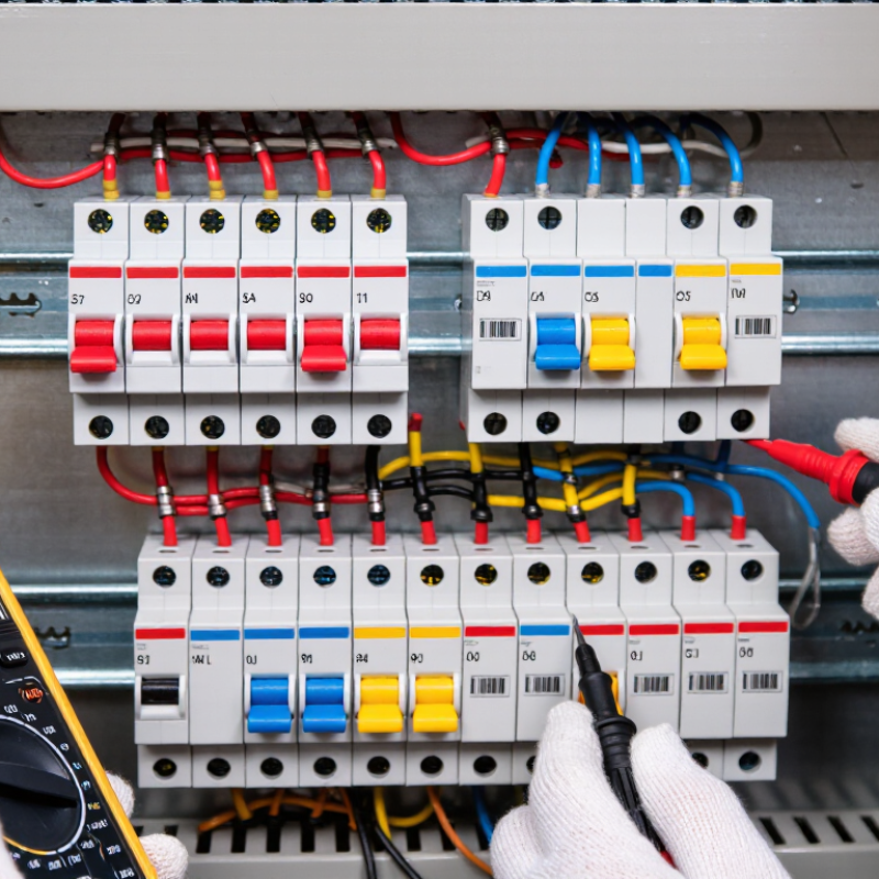
An ELCB circuit breaker protects people and equipment by detecting unwanted current flowing toward earth. When leakage rises above its set threshold, the device disconnects the circuit rapidly. That action can reduce shock risk and limit insulation-related fire hazards. It does not make an installation automatically safe.
Older voltage-operated ELCBs monitor voltage on the protective earth conductor. Modern residual-current devices usually compare current leaving and returning through the circuit. A small imbalance signals leakage, even when the appliance still appears to work normally. This distinction matters. During practical checks, I look for the test button, clear labels, secure earthing, and signs of heat. Pressing the test button should trip the device. Reset it only after considering the cause. A failed test is not a minor inconvenience. It needs prompt investigation by a competent electrician.
Choose the device according to rated current, residual operating current, pole arrangement, supply system, and expected load. Sensitive protection may nuisance-trip where equipment creates normal leakage. Less sensitive protection may leave people exposed. That trade-off is easy to underestimate. An ELCB also cannot replace overcurrent protection, so a suitable circuit breaker may still be required. Selection should follow local electrical rules and the installation design, not a label alone. I would recheck the choice after measuring real leakage, because assumptions often fail in occupied buildings.
Choosing an ELCB begins with the actual electrical risk, not the device label. “ELCB” can describe older voltage-operated protection or modern residual-current protection. Confirm the device type before comparing specifications. A qualified electrician should inspect the distribution board, earthing system, and connected circuits.
List every load involved. Water heaters, outdoor sockets, bathrooms, kitchens, and garden equipment often need stronger leakage protection. A 30 mA residual-current setting is commonly used for supplementary protection against electric shock, but local electrical rules must guide the final choice. Higher sensitivity may create nuisance trips when equipment has normal leakage. Lower sensitivity may provide inadequate personal protection.
Check the rated voltage, current, number of poles, breaking capacity, and residual-current rating. The breaker must match the circuit conductors and expected load. It should also coordinate with upstream overcurrent protection. A residual-current device does not automatically replace a fuse or miniature circuit breaker.
Dust, moisture, heat, and outdoor exposure can affect reliability. Select an enclosure and device suitable for those conditions. Test the unit with its test button at the recommended interval, and record the result. A silent test button is not proof of safety.
The perfect selection on paper can still fail through poor wiring. Shared neutral conductors, loose terminals, and incorrect earthing commonly cause unwanted trips. Do not ignore them. Have installation and testing completed by a competent professional under applicable local standards.
An ELCB may detect earth leakage by voltage or by current. Older voltage-operated units sense a voltage rise between the equipment earth and a reference point. They depend on a sound earth connection, so a broken or bypassed earth path can undermine protection. Current-operated ELCBs, commonly called RCDs or RCCBs, compare current in the live and neutral conductors. A mismatch indicates leakage, even when the fault path does not raise the local earth voltage. That difference matters in real installations. A damp garage socket and a long outdoor cable can create leakage paths that are hard to spot by inspection alone.
Check the device’s rated residual operating current, pole arrangement, and compatibility with the circuit. For additional protection against electric shock, IEC 60364-4-41 specifies 30 mA RCD protection for selected circuits, including many socket-outlet circuits. The IEC 61008-1 product standard also defines operating-time tests; at five times rated residual current, the maximum operating time for a general, non-delay RCCB is 40 milliseconds.
These figures are not a substitute for choosing the right device type: some electronic loads produce pulsating or smooth DC residual currents, which may require different detection capability. Confirm the load profile and installation requirements with a qualified electrician, then test the installed device using its test button and the manufacturer’s instructions.
How to Choose the Right ELCB Circuit Breaker?
Choosing an ELCB starts with the electrical system, not the product appearance. Check the supply voltage, frequency, and number of poles before comparing models. An ELCB rated for 230 volts should match a 230-volt circuit. A voltage mismatch can cause unreliable operation or equipment damage. Confirm the marking carefully.
Rated current must suit both the expected load and the cable capacity. Add the normal operating currents, then consider motors, heaters, or other temporary surges. Do not select a higher current rating simply to prevent nuisance tripping. In panel inspections, I have seen oversized breakers leave undersized cables poorly protected. More is not always safer. A qualified electrician should verify the calculation against local requirements.
Trip sensitivity is measured in milliamperes and indicates the leakage current that triggers disconnection. A 30 mA setting is commonly used for additional personal protection, while higher settings may support fire protection or selective coordination. The correct value depends on the circuit, grounding arrangement, equipment leakage, and applicable codes. Check the time-current data, not only the sensitivity printed on the front. Press the test button regularly, but remember that this checks the mechanism, not every installation condition. I have seen test buttons work while loose terminals remained unnoticed. That detail deserves attention.
How to Choose the Right ELCB Circuit Breaker?
Verify the installation standard before comparing prices or features. Check the electrical code used in your country, then confirm the ELCB’s rated voltage, current, breaking capacity, and residual operating current. These values must match the circuit’s design. A domestic lighting circuit may need different protection from a workshop outlet circuit. Ask a qualified electrician to inspect the earthing arrangement, conductor size, and neutral connection. Incorrect wiring can leave the test button working while protection remains incomplete.
Installation details matter. The device should fit the distribution board, with clear line and load markings. Tighten terminals to the manufacturer’s specified torque. Loose connections can create heat, discoloration, or intermittent trips. The enclosure should also suit its environment, especially where dust or moisture is present. A clean panel is not proof of a safe installation. That assumption is easy to make.
Tips: Press the test button at the interval required by local rules, and record the result. Arrange professional testing with suitable equipment during scheduled inspections. Look for unusual warmth, burning smells, nuisance trips, or a test button that does nothing. Replace damaged units promptly. Maintenance records help reveal recurring faults, although they are often incomplete. Review them honestly. Safety depends on the whole installation, not the breaker alone.
Verify Installation Standards and Maintenance Needs
The chart shows the maximum operating time commonly specified for instantaneous residual-current circuit breakers at different multiples of their rated residual operating current. A suitable ELCB should match the system voltage, earthing arrangement, rated current, residual-current sensitivity, and required disconnection time. Installation verification should include protective-conductor continuity, insulation resistance, polarity, automatic disconnection, and functional testing. Maintenance should follow the applicable electrical standard and the device manufacturer’s instructions; test-button checks alone do not replace periodic instrument testing.
„Thanks to the LUVIR technology, the solder resist process could be switched directly from the previously used mask exposure to direct exposure. As an outstanding digital solution on the market, this technology has been able to demonstrate fast process times and superior quality on our certified conventional ink in production. This allowed us to fully digitize the solder mask process at low cost – without process or ink adjustments. An excellent benefit to our production in Rot am See.“
Ralf Göhringer (Head of Production WE Rot am See)
I would definitely recommend the Limata machine and team for a future company purchase
Michael Greenaway
Compunetics Inc.
“The Limata ldi has been amazing!! Best thing we did was buy this machine”
Richard Brady
GM
Circuitlabs
“Since 2019, we have been running the Limata X1000 LDI system (including LUVIR for solder mask imaging) in daily production as an addition to our current process with film. The machine was capable of properly exposing Taiyo PSR-4000 BN (DI) solder mask types on normal to high-copper boards using a new and unique direct imaging process. The machine operating interface is very user friendly which allowed for a quick technical training curve. The pre-registration processing reduced several seconds of production time at every print. Limata support and service staff is incomparable. They supported our team every step of the way at basically any time of the day or night, with literally, an immediate response time, customizing the software interface to best fit our Operations and needs.
We have exposed more than 8,000 prints since end of October, on various solder mask colors and some resist film panels. Limata, has proven to be very capable and innovative. They are a strong contender in the industry.
We have very much enjoyed this project, and working with the team!
Thank you Limata for the continued support and being a part of our growth.”
Bill Sezate
Vice President, GM
Summit Interconnect
As a replacement to our current contact exposure process with film, the LIMATA X2000 system including LUVIR-Technology was capable of properly exposing non-LDI solder mask types using a direct imaging process. The machine offers cutting edge software with a very intuitive operating interface which allowed for quick technician training curve. The dual drawer system combined with pre-registration processing reduced several seconds of production time at every machine cycle. Limata support and service staff is world class. They added software patches to keep production running at shortest possible response times, customized the software interface to best fit our in-house Operations system, and even wrote a step-by-step machine processing manual. As a result of the project, we have exposed more than 16,000 times on various product types and solder mask brands/colors. Limata, in a very short timeframe as a company, has definitely shown they are truly innovative and will be challenging the industry of direct imaging for the top spot.
Kevin Beattie
Process Engineer
TTM Technologies
Forest Grove Division