Choosing a USB C Bulkhead Connector in 2026 is not just a matter of matching plug shapes. The right part must fit the panel, cable, and job it will perform. A connector mounted through a thin aluminum enclosure may need different hardware from one installed in a thick instrument panel. Small details matter.
Start with the required function. USB-C describes the connector shape, but it does not guarantee a particular data rate, charging level, or video capability. Check the manufacturer’s datasheet for supported performance, pin configuration, and cable compatibility. If the port will face dust, moisture, or frequent cleaning, review its stated ingress protection rating and installation conditions. Do not assume a sealed-looking cap makes the complete assembly waterproof.
Mechanical fit matters just as much. Confirm the panel cutout diameter, panel thickness range, mounting method, and clearance behind the enclosure. A right-angle cable may solve a tight-space problem, but it can also put extra strain on the port. Check connector orientation and how users will grip the plug. Awkward access is easy to miss on a drawing.
Test the actual setup. A sample fitted to the enclosure can reveal alignment issues, loose mounting, or a cable that will not seat fully. That sounds simple. It is often overlooked. Compare operating conditions, expected mating cycles, and warranty terms before choosing a supplier. No single USB C Bulkhead Connector suits every installation, and datasheets may not answer every practical question. Leave room for verification rather than relying on the product title alone.
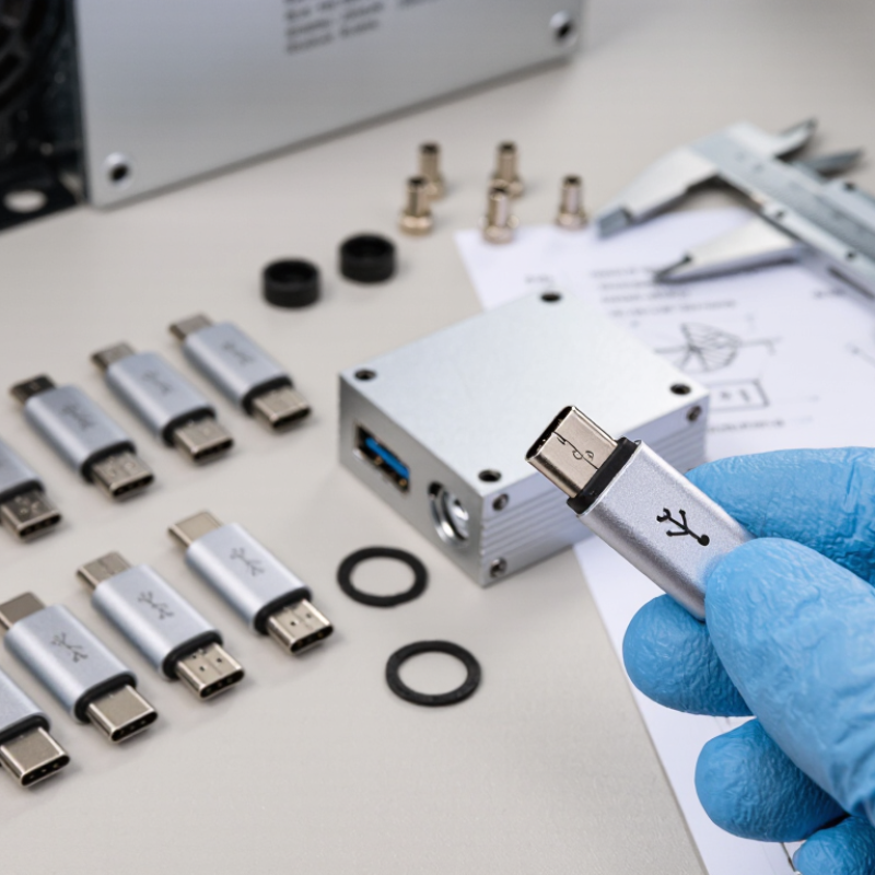
A USB-C bulkhead connector passes through an enclosure wall while keeping a port accessible outside. Common options include panel-mount feedthroughs, cable-to-panel assemblies, and sealed connectors for exposed environments. Choose by installation and use, not appearance alone. A compact feedthrough may suit a control box, while a cable assembly can simplify internal routing. USB-C describes the connector shape, not guaranteed data speed or power capacity. Check the actual specifications.
Look closely at the components. The metal shell provides mechanical support, and the insulating body separates the contact pins. Contacts carry power and data; their layout and rating affect performance. A gasket helps limit dust and moisture entry, but only when the panel thickness, mounting surface, and compression match its design. The retaining nut or flange keeps the connector stable. Small details matter.
Match the connector’s data standard, current rating, and voltage requirements to the connected equipment. Also check whether it supports the intended USB functions; a physical fit does not prove compatibility. For outdoor or washdown use, review the stated protection rating and installation conditions rather than relying on a rubber ring’s appearance. One easy mistake is overlooking the cable’s bend space behind the panel. Measure it before cutting. I would still verify the drawings against the enclosure, because dimensions can be interpreted differently.
A USB-C bulkhead connector should be chosen from measured requirements, not its shape. Record the maximum voltage, continuous current, and charging profile before comparing parts. The USB Implementers Forum’s USB Power Delivery Specification Revision 3.1 defines power delivery up to 240 W. That figure is a system capability, not a promise that every connector or cable can carry it. Check the connector’s rated current, temperature rise, and mating-cycle data against your real load. A warm panel can reveal a poor match.
For data, identify the required protocol and speed, then verify the complete connector-and-cable assembly. USB-IF’s USB 3.2 specification defines signaling rates up to 20 Gbps, while USB4 Version 2.0 supports up to 80 Gbps. Higher rates leave less room for signal loss. Small details matter. Confirm shielding continuity, differential-pair routing, and any required impedance or insertion-loss limits in the supplier’s test data. If the port also carries DisplayPort or other alternate-mode signals, confirm those lanes are supported through the bulkhead.
List control and accessory signals too, such as USB 2.0 D+/D−, configuration-channel pins, and sideband lines. Then check whether the chosen wiring preserves their function. A common oversight is testing only charging. Bench-test the assembled panel with the intended host, cable length, and device; real installations can behave differently from a tidy lab setup.
A USB-C bulkhead connector sits at the boundary between equipment and its surroundings, so its ratings must fit the real installation. For a damp enclosure, check the stated ingress protection rating and confirm whether it applies when the connector is mated, capped, or both. A gasket can help, but a poorly cut panel or uneven mounting surface may still let moisture in. Small details matter. In dusty or washdown areas, verify the manufacturer’s test conditions rather than assuming a high rating covers every exposure. Also compare the specified operating temperature with expected heat from nearby electronics and direct sunlight.
Outdoor and mobile installations need more than a water rating. Check corrosion resistance, vibration limits, panel thickness, and cable strain relief; a heavy cable can loosen a connector over time. Match the connector’s current and voltage limits to the device, and confirm that its data capability supports the required USB speed. Check the datasheet. I would not treat “USB-C” as proof of identical performance across connectors. No rating is universal. Installation quality matters too, and it is easy to overlook that until a seal fails or a cable starts pulling against the panel.
How to Choose a USB C Bulkhead Connector in 2026?
Check Panel Fit, Mounting, and Cable Compatibility
Measure the panel opening and thickness before selecting a connector. A cutout that is slightly too small can leave the connector tilted; one that is too large may prevent a secure seal. Check the mounting depth behind the panel, too. Nearby ribs, screws, or a tight enclosure can block the connector’s rear body or cable bend. Small details matter. Confirm the required cutout dimensions against the product drawing, not just a photo.
Tips: Test the connector on a scrap panel of similar thickness. Check that the retaining nut tightens fully and any gasket sits flat. If the panel is curved or textured, allow extra time for fit checks; seals do not compensate for uneven contact.
Then match the connector’s cable arrangement to your actual setup. Some bulkhead connectors have a short internal lead, while others accept a cable directly. Verify connector ends, cable length, and supported data rate or charging power. A USB-C-shaped connection alone does not guarantee a particular speed or power level. Check both sides. I would also recheck clearance with the enclosure closed; that step is easy to miss, and cable bends can put strain on the connection.
Check panel fit, mounting, and cable compatibility. The chart shows the nominal maximum data rates of selected USB data standards commonly carried over USB-C; the connector alone does not determine performance.
Before ordering, measure the panel cutout and thickness, confirm the connector’s mounting method and clearance, and verify that the bulkhead assembly supports the required USB data standard. Check the attached cable and both connected devices too: the actual link is limited by the capabilities of the complete connection.
Choose the connector against the whole assembly, not its USB-C shape. The USB Implementers Forum’s USB Power Delivery 3.1 specification supports up to 240 W, but a bulkhead connector may not. Confirm its rated voltage and current, supported data rate, and compatibility with the cable and device. USB-C alone does not guarantee a particular charging or data performance.
Check the mating face. IEC 60529 defines ingress-protection ratings; an IP67 claim means dust-tight protection and tested temporary immersion under specified conditions. It does not guarantee the same protection after poor panel installation or a damaged seal.
Ask suppliers for the test conditions, panel-thickness range, operating temperature, and mating-cycle rating. Request the cycle-test method, too; figures are hard to compare without one. A useful specification also includes contact resistance and the change measured after durability testing.
A high rating can look reassuring, yet the seal may be the weak point. I would pause there. Compare the actual datasheet with your enclosure, cable, and expected handling—not just a headline rating.
„Thanks to the LUVIR technology, the solder resist process could be switched directly from the previously used mask exposure to direct exposure. As an outstanding digital solution on the market, this technology has been able to demonstrate fast process times and superior quality on our certified conventional ink in production. This allowed us to fully digitize the solder mask process at low cost – without process or ink adjustments. An excellent benefit to our production in Rot am See.“
Ralf Göhringer (Head of Production WE Rot am See)
I would definitely recommend the Limata machine and team for a future company purchase
Michael Greenaway
Compunetics Inc.
“The Limata ldi has been amazing!! Best thing we did was buy this machine”
Richard Brady
GM
Circuitlabs
“Since 2019, we have been running the Limata X1000 LDI system (including LUVIR for solder mask imaging) in daily production as an addition to our current process with film. The machine was capable of properly exposing Taiyo PSR-4000 BN (DI) solder mask types on normal to high-copper boards using a new and unique direct imaging process. The machine operating interface is very user friendly which allowed for a quick technical training curve. The pre-registration processing reduced several seconds of production time at every print. Limata support and service staff is incomparable. They supported our team every step of the way at basically any time of the day or night, with literally, an immediate response time, customizing the software interface to best fit our Operations and needs.
We have exposed more than 8,000 prints since end of October, on various solder mask colors and some resist film panels. Limata, has proven to be very capable and innovative. They are a strong contender in the industry.
We have very much enjoyed this project, and working with the team!
Thank you Limata for the continued support and being a part of our growth.”
Bill Sezate
Vice President, GM
Summit Interconnect
As a replacement to our current contact exposure process with film, the LIMATA X2000 system including LUVIR-Technology was capable of properly exposing non-LDI solder mask types using a direct imaging process. The machine offers cutting edge software with a very intuitive operating interface which allowed for quick technician training curve. The dual drawer system combined with pre-registration processing reduced several seconds of production time at every machine cycle. Limata support and service staff is world class. They added software patches to keep production running at shortest possible response times, customized the software interface to best fit our in-house Operations system, and even wrote a step-by-step machine processing manual. As a result of the project, we have exposed more than 16,000 times on various product types and solder mask brands/colors. Limata, in a very short timeframe as a company, has definitely shown they are truly innovative and will be challenging the industry of direct imaging for the top spot.
Kevin Beattie
Process Engineer
TTM Technologies
Forest Grove Division