Choosing the best Analog Splitter 4 20ma requires more than comparing catalog prices. The correct device must preserve signal accuracy while feeding multiple control, monitoring, or recording systems. A practical selection begins with the transmitter output, available loop power, receiver impedance, and required isolation level.
Béla G. Lipták, a respected process-instrumentation authority, emphasizes this principle: “The transmitter is only one part of the measurement system.” His observation remains valuable when a 4–20 mA loop passes through several devices. A splitter that appears suitable may introduce burden voltage, electrical noise, or unacceptable conversion error.
Check the details.
For example, a 24 VDC loop may struggle when two receivers each add significant resistance. A 250-ohm input consumes 5 volts at 20 mA, before cable losses and protection components are considered. Galvanic isolation also matters when separate cabinets use different ground references. Without it, a stable pressure signal can become a fluctuating trend on the control screen.
Look for published accuracy, temperature drift, response time, and isolation ratings. Confirm whether the Analog Splitter 4 20ma accepts active, passive, or loop-powered inputs. Installation conditions deserve equal attention. Dust, vibration, moisture, and cabinet temperature can expose weaknesses hidden in laboratory specifications.
Experience complicates the decision. The highest accuracy model is not always the best choice. It may consume more power or require unnecessary configuration. Conversely, a low-cost unit may work perfectly in a short cabinet run, but fail in a noisy plant environment. Recheck the datasheet, wiring diagram, and receiver burden before ordering. Small assumptions can become expensive field corrections.
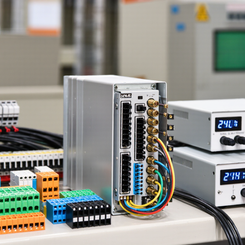
Choosing the best analog splitter starts with defining its role, not searching a catalog. A 4–20 mA splitter receives one transmitter signal and creates two or more isolated outputs. Each output may serve a PLC, display, recorder, or safety system. Confirm this path on a loop drawing. Check active or passive inputs, input resistance, isolation voltage, accuracy, response time, and power supply. A splitter can fit perfectly yet overload the loop. This mistake appears often during field retrofits.
A 2024 smart-manufacturing survey reported that 86% of manufacturers view smart operations as a major competitiveness driver. More connected loops require clearer signal management. The NE 43 process guideline identifies signals below 3.6 mA or above 21.0 mA as possible fault conditions, depending on configuration. The splitter must reproduce or clearly flag these values. Test zero, span, cable resistance, and alarm thresholds with a calibrated current source. I once treated isolation as a checkbox. The wiring looked correct, but a shared supply caused unwanted interaction. That failure changed my checklist. Also define temperature, humidity, maintenance access, and hazardous-area requirements. Leave room for drift and future channels.
Define the role and requirements of a 4–20 mA analog splitter by checking the voltage developed across the receiver load. The values below are calculated using Ohm’s law: V = I × R.
A 250 Ω load converts 4–20 mA into 1–5 V, while a 500 Ω load converts it into 2–10 V. Higher resistance requires more compliance voltage from the splitter, so verify the splitter’s loop-power capacity, input range, output isolation, accuracy, and load limit before selection.
How to Choose the Best Analog Splitter 4 20mA?
Compare the input range before checking price or enclosure size. A splitter should accept the transmitter’s full 4–20 mA loop without clipping. IEC 60381-1 treats 4 mA as the live zero and 20 mA as the upper signal point. Confirm whether the device supports active, passive, or loop-powered input. This detail often causes installation mistakes. A two-channel output may provide separate signals for a controller and a recorder. Check output loading carefully. For example, a 20 mA output driving a 500-ohm load needs 10 volts of compliance. The numbers look small. They are not.
Signal isolation deserves equal attention. Look for input-to-output and output-to-output isolation ratings, not only the word “isolated.” A 2.5 kVrms test rating is common, but continuous working voltage can be much lower. NAMUR NE 43 identifies approximately 3.6 mA and 21.0 mA as useful fault thresholds. Your splitter should preserve these conditions, or clearly document its fault behavior. Industry process-automation surveys repeatedly identify grounding problems and cabinet noise as major causes of analog signal errors. That matches field experience, although survey methods vary. Accuracy around 0.1% is often adequate, but temperature drift may quietly exceed it. Test the splitter at 4, 12, and 20 mA, then repeat the test after warm-up. I would not trust a datasheet alone.
| Specification | Passive 1-in / 2-out | Active 1-in / 2-out | Active 1-in / 3-out | Isolated 1-in / 2-out | Selection Guidance |
|---|---|---|---|---|---|
| Input signal | 4–20 mA, 2-wire transmitter loop | 4–20 mA, 2-wire or 4-wire input | 4–20 mA, 2-wire or 4-wire input | 4–20 mA, 2-wire or 4-wire input | Confirm the splitter accepts the transmitter wiring method used in the control loop. |
| Input range | 3.6–21.0 mA typical | 0–22 mA typical | 0–22 mA typical | 0–22 mA typical | A wider range can accommodate underrange, overrange, and diagnostic current levels. |
| Output configuration | 2 × 4–20 mA, passive | 2 × 4–20 mA, active | 3 × 4–20 mA, active | 2 × 4–20 mA, independently powered | Choose the number and electrical type of outputs required by meters, PLCs, DCSs, or recorders. |
| Output load capacity | Up to approximately 350 Ω per output, installation-dependent | Up to 500 Ω per output at 20 mA | Up to 500 Ω per output at 20 mA | Up to 500 Ω per output at 20 mA | Calculate total loop resistance, including cable, input resistance, and safety barriers. |
| Power requirement | Powered by the input loop; no separate supply normally required | 18–30 V DC | 18–30 V DC | 18–30 V DC, typically separate from the signal loop | Check available control-panel power and voltage tolerance before selecting an active unit. |
| Signal isolation | Not provided; common electrical path | Typically no galvanic isolation between input and outputs | Typically no galvanic isolation between input and outputs | Input-to-output and output-to-output isolation, commonly 1.5–2.5 kV AC test rating | Use an isolated model to prevent ground loops and protect separate systems with different ground potentials. |
| Accuracy | Typically ±0.2% of span | Typically ±0.1% of span | Typically ±0.1% of span | Typically ±0.1% to ±0.2% of span | Include temperature drift and calibration tolerance when high accuracy is required. |
| Linearity | Typically ±0.1% of span | Typically ±0.05% of span | Typically ±0.05% of span | Typically ±0.05% to ±0.1% of span | Lower linearity error improves measurement consistency across the full 4–20 mA range. |
| Response time | Typically 10–30 ms | Typically 5–20 ms | Typically 5–20 ms | Typically 5–25 ms | Select a faster response for process control or rapidly changing measurements. |
| Output ripple and noise | Typically below 20 mV peak-to-peak | Typically below 10 mV peak-to-peak | Typically below 10 mV peak-to-peak | Typically below 10–20 mV peak-to-peak | Lower noise is preferable for long cable runs and sensitive analog input cards. |
| Operating temperature | Approximately −20 to +60 °C | Approximately −20 to +60 °C | Approximately −20 to +60 °C | Approximately −20 to +60 °C | Verify the rated temperature range against the control cabinet environment. |
| Installation format | Compact DIN-rail or panel-mounted module | DIN-rail module | DIN-rail module | DIN-rail module with reinforced creepage and clearance | Check available cabinet width, terminal orientation, and wiring access. |
| Typical application | Simple signal duplication where all devices share a common ground | General PLC, DCS, meter, and recorder signal distribution | One transmitter feeding three monitoring or control destinations | Ground-loop prevention, hazardous-area interfaces, and electrically separate systems | Match the splitter type to the grounding, power, and channel-count requirements of the installation. |
Note: The values shown are representative specification ranges for common industrial 4–20 mA splitter categories. Always verify the final device datasheet, loop-power budget, load resistance, isolation test voltage, and environmental ratings before installation.
Accuracy is the first practical test. A splitter should preserve the transmitter’s 4–20 mA range without adding noticeable drift. IEC 60381-1 defines 4 mA as the live zero and 20 mA as the upper signal limit. For demanding temperature or pressure loops, target accuracy near ±0.1% of span. Check whether this figure includes temperature effects, calibration error, and isolation. Some datasheets separate these values. That can mislead hurried buyers.
Load capacity matters just as much. A 250-ohm receiving instrument needs 5 V at 20 mA, based on Ohm’s law. Two similar outputs may require 10 V, plus wiring resistance and safety margin. A 2023 industrial automation survey published by Control Engineering reported that signal reliability remains a major concern in process measurement projects. The survey did not prove every failure came from loading, but the warning is useful. Calculate each output independently. Do not trust a single headline rating.
Power compatibility deserves a bench check. Many splitters accept 24 VDC, yet their operating range, reverse-polarity protection, and current consumption differ. A 24 V supply may fall below 20 V during startup or long cable runs. Select a unit with adequate compliance voltage and documented isolation between input, outputs, and supply. IEC 61010-1 guidance also makes spacing and protection relevant in industrial cabinets. I would test the splitter at 20 mA, maximum load, and the highest enclosure temperature. Real cabinets are rarely as cool as the laboratory.
How to Choose the Best Analog Splitter 4 20mA?
Start with the installation conditions, not the product label. Check the transmitter’s loop voltage, ambient temperature, humidity, and available cabinet space. A splitter must handle the full signal range without reducing loop power. Measure the receiving device’s input resistance before selection. This small step prevents unstable readings later. I have seen a 4–20mA loop fail because the total load was underestimated.
Wiring methods also affect measurement quality. Use twisted, shielded cable for long signal runs, especially near motors or switching equipment. Keep signal wires separate from power cables. Confirm whether the splitter needs two-wire or four-wire wiring. Observe polarity at every terminal. One reversed connection can stop the entire loop. Ground the shield at one point only, unless the equipment documentation states otherwise. Galvanic isolation is valuable when different instruments use separate power supplies.
Tips: Check terminal labels twice. Test each channel with a calibrated current source. Record the measured output at 4mA, 12mA, and 20mA. Leave enough cabinet space for ventilation and maintenance. Do not assume every splitter is protected against surges, reverse polarity, or short circuits. Review these safety features carefully. A perfect installation is rare, and my own early designs sometimes ignored future maintenance access. That mistake made simple testing unnecessarily difficult.
How to Choose the Best Analog Splitter 4 20mA?
Selecting an analog 4-20mA splitter requires more than comparing prices. Check signal accuracy, isolation, response time, and acceptable load resistance. A splitter with 0.1% accuracy may suit precise control, while 0.5% accuracy could work for basic monitoring. Confirm the input and output ranges match your transmitter and control system. A mismatch can create unstable readings.
Reliability matters in real installations. Look for electrical isolation between channels, protection against overvoltage, and stable performance across temperature changes. In a control cabinet, vibration, heat, and electrical noise are common. Choose terminals that are easy to access and a housing that fits securely on the rail. Test the splitter with a calibrated current source before commissioning. I have seen small wiring errors cause larger faults than poor specifications. Documentation should include wiring diagrams, calibration data, and operating limits. Do not trust a vague datasheet.
Tips: Compare total cost, not only the purchase price. Include installation time, calibration needs, energy use, and possible downtime. Keep spare units only when replacement delays could affect production. A low-cost splitter may seem attractive, but frequent recalibration can remove its advantage. Conversely, the most expensive model may provide features your system never uses. Review actual plant conditions, record test results, and ask whether each specification solves a real problem. Perfect selection is unlikely. Careful verification is practical.
„Thanks to the LUVIR technology, the solder resist process could be switched directly from the previously used mask exposure to direct exposure. As an outstanding digital solution on the market, this technology has been able to demonstrate fast process times and superior quality on our certified conventional ink in production. This allowed us to fully digitize the solder mask process at low cost – without process or ink adjustments. An excellent benefit to our production in Rot am See.“
Ralf Göhringer (Head of Production WE Rot am See)
I would definitely recommend the Limata machine and team for a future company purchase
Michael Greenaway
Compunetics Inc.
“The Limata ldi has been amazing!! Best thing we did was buy this machine”
Richard Brady
GM
Circuitlabs
“Since 2019, we have been running the Limata X1000 LDI system (including LUVIR for solder mask imaging) in daily production as an addition to our current process with film. The machine was capable of properly exposing Taiyo PSR-4000 BN (DI) solder mask types on normal to high-copper boards using a new and unique direct imaging process. The machine operating interface is very user friendly which allowed for a quick technical training curve. The pre-registration processing reduced several seconds of production time at every print. Limata support and service staff is incomparable. They supported our team every step of the way at basically any time of the day or night, with literally, an immediate response time, customizing the software interface to best fit our Operations and needs.
We have exposed more than 8,000 prints since end of October, on various solder mask colors and some resist film panels. Limata, has proven to be very capable and innovative. They are a strong contender in the industry.
We have very much enjoyed this project, and working with the team!
Thank you Limata for the continued support and being a part of our growth.”
Bill Sezate
Vice President, GM
Summit Interconnect
As a replacement to our current contact exposure process with film, the LIMATA X2000 system including LUVIR-Technology was capable of properly exposing non-LDI solder mask types using a direct imaging process. The machine offers cutting edge software with a very intuitive operating interface which allowed for quick technician training curve. The dual drawer system combined with pre-registration processing reduced several seconds of production time at every machine cycle. Limata support and service staff is world class. They added software patches to keep production running at shortest possible response times, customized the software interface to best fit our in-house Operations system, and even wrote a step-by-step machine processing manual. As a result of the project, we have exposed more than 16,000 times on various product types and solder mask brands/colors. Limata, in a very short timeframe as a company, has definitely shown they are truly innovative and will be challenging the industry of direct imaging for the top spot.
Kevin Beattie
Process Engineer
TTM Technologies
Forest Grove Division