Choosing the right Hydraulic Seal is essential for safe, efficient, and reliable fluid power equipment. A seal may look like a small component, yet it controls leakage, protects internal parts, and supports consistent pressure. In a working cylinder, the seal faces heat, friction, pressure changes, and contaminated oil. A poor match can cause damaged rods, sudden performance loss, or repeated maintenance.
This guide explains the practical factors behind a dependable seal selection. Material compatibility matters. So does pressure. You must also check temperature, fluid type, shaft speed, groove dimensions, and installation conditions. Polyurethane may suit demanding hydraulic applications, while PTFE can perform well under higher temperatures and chemical exposure. However, no material works perfectly in every environment. That detail is often missed.
Experienced technicians usually inspect the original seal, measure the housing, and review the equipment manual before ordering replacements. They also examine wear patterns. A torn lip may indicate poor installation, excessive pressure, or surface damage rather than simple seal aging. Small clues matter.
The process is not always straightforward. Some equipment has incomplete records, and field measurements may be imperfect. Therefore, selection should combine manufacturer data, application experience, and verified dimensions. When uncertainty remains, consult a qualified seal supplier or hydraulic engineer. A careful choice costs less than repeated downtime. This guide will help you compare seal profiles, materials, designs, and operating conditions with greater confidence.
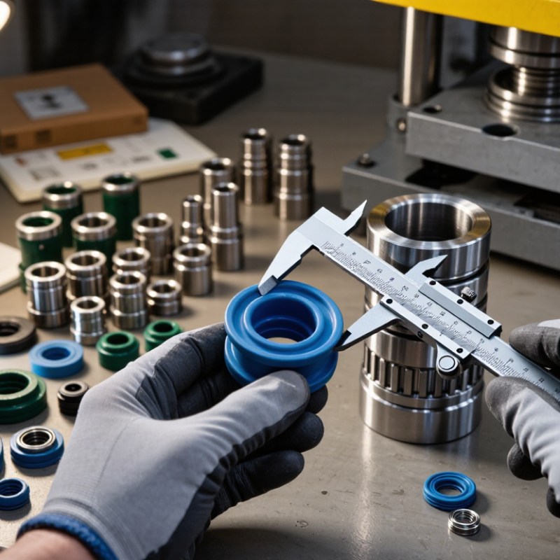
Choosing the right hydraulic seal starts with operating conditions, not catalog shape. Record maximum and continuous pressure at the actual cylinder port. A gauge reading of 160 bar may hide pressure spikes during impact. Note whether pressure is static, reciprocating, or rapidly reversing. Pressure rating alone is insufficient. Confirm extrusion gaps, housing clearance, and backup-ring requirements using engineering drawings and recognized seal specifications.
Measure fluid and nearby surface temperatures after sustained operation. Short cold starts can behave differently from a warm afternoon cycle. Select material for continuous temperature, peak temperature, and exposure time. Then calculate rod or piston speed from stroke length and cycle time. Fast motion can generate heat, while slow motion may cause stick-slip. Check lubrication and surface finish. A polished rod is not automatically suitable. Small scratches matter.
Identify the exact fluid, additives, water content, and cleaning chemicals. Compatibility charts help, but service testing is more dependable when uncertainty remains. Request immersion data at the working temperature. In field repairs, seals often fail because the fluid changed, not because installation was careless. I have seen a replacement pass pressure testing but leak after several hours. That result deserves investigation. Review groove dimensions, compression, installation tools, and contamination control. Leave room for doubt. Operating conditions rarely stay perfect.
Define pressure, temperature, speed, and fluid requirements before selecting the seal material.
Choosing a hydraulic seal starts with temperature, fluid, pressure, and movement. NBR commonly operates from -30°C to 100°C. It suits mineral oils and general industrial cylinders. Polyurethane usually covers about -30°C to 100°C. It offers strong abrasion resistance during frequent reciprocating motion. FKM handles roughly -20°C to 200°C. It performs well with heat, fuels, and aggressive oils. PTFE supports approximately -200°C to 260°C. Its low friction is valuable in high-speed or chemically demanding applications. These ranges come from commonly published engineering data referenced by ASTM D2000 and ISO 23936-2:2011. Actual limits change with compound, pressure, and installation.
Temperature is only one part.
Field inspections often show premature wear from poor groove design, not weak material. NBR may harden near hot oil. Polyurethane can swell in incompatible fluids. FKM may lose flexibility at low temperatures. PTFE reduces friction, but it needs suitable energizing support because it lacks rubber-like elasticity. A 2023 technical report from the International Sealing Distribution Association stresses verification through application testing, rather than relying on catalog ranges alone. That caution matters. Real cylinders experience pressure spikes, contamination, and imperfect alignment.
Tips: Match the seal to the actual fluid and duty cycle. Check the manufacturer’s compound data against ISO 23936-2 compatibility guidance. For abrasive, fast-moving rods, test polyurethane first. For extreme heat, review FKM and PTFE options. Measure groove dimensions carefully. A small design error can defeat an excellent material.
How to Choose the Right Hydraulic Seal?
Select ISO 3601 O-rings by groove size, pressure, and tolerance. Start with the groove, not the seal bag. Measure groove diameter, width, depth, and surface finish with calibrated tools. ISO 3601-1 defines O-ring dimensions and dimensional tolerances, while ISO 3601-2 provides housing design guidance. A small depth error can reduce squeeze and cause leakage. Measure twice.
Pressure changes the design decision. Check the actual working pressure, pressure spikes, temperature, fluid type, and extrusion gap. ISO 3601-3 classifies visible surface imperfections and acceptance criteria, but it does not guarantee performance in every hydraulic assembly. That distinction matters. A seal may pass inspection yet fail under rapid cycling. Industry hydraulic safety guidance commonly treats contamination, poor finish, and excessive clearance as major reliability risks. Use a back-up ring when the pressure and extrusion gap require it. Confirm the recommendation against the equipment manufacturer’s engineering data.
Tolerance selection needs restraint. Excessive squeeze increases friction and heat; insufficient squeeze permits leakage during low pressure or thermal movement. ISO 3601 tolerances should guide the seal selection, while the groove tolerance controls the real installation result. I have found that drawings often hide worn bores or rounded groove edges. That is an uncomfortable gap in the process. Record measurements from several positions, then compare them with ISO 3601 housing limits and the seal supplier’s pressure tables. Test with the real fluid whenever possible. Static success is not enough.
Pressure changes the seal design, not just the material choice. At 100 bar, a standard elastomeric seal may perform well with controlled clearances and moderate speed. Near 250 bar, extrusion risk becomes more serious. A backup ring or reinforced sealing profile may be necessary. At 400 bar, consider a guided, low-clearance design with stronger anti-extrusion support. ISO 6022 defines hydraulic cylinders for pressures up to 250 bar, showing why 400-bar service demands careful engineering beyond common cylinder practice.
Industry data also supports a disciplined selection process. The National Fluid Power Association’s 2024 Fluid Power Industry Statistical Handbook tracks hydraulic equipment demand across mobile and industrial applications. Its market coverage reflects a practical reality: operating conditions vary widely, even within the same pressure range.
Pressure alone is not enough. Check temperature, piston speed, fluid type, surface finish, and radial clearance. ISO 3601 provides dimensional guidance for O-rings, but it does not guarantee performance at every pressure.
I have seen seals fail below their advertised rating. The cause was often excessive clearance during pressure spikes. A 100-bar system may briefly exceed that level. Measure the housing accurately. Confirm the pressure peak, not only the gauge average. For 400-bar applications, test the complete seal arrangement under real cycling conditions. A perfect-looking profile can still fail after heat, contamination, and repeated load changes. That uncomfortable detail matters.
A hydraulic seal should be selected from measured conditions, not a catalog picture. Verify the seal material, working temperature, pressure, fluid, speed, and movement type. Then review its ISO 815 compression set data. This test measures how much sealing material remains permanently deformed after compression, heat, and a controlled period. Lower recovery can reduce sealing force over time. That matters during cold starts and long service intervals.
Ask for the test temperature, test duration, specimen type, and reported result. Numbers without conditions can mislead. Compare the report with your actual operating environment. A seal tested at one temperature may behave differently near a hot cylinder head. Check the production lot, too. Laboratory results are useful, but they are not the whole decision.
Installation requirements deserve equal attention. Confirm groove width, depth, seal squeeze, housing tolerances, and surface finish. Remove sharp edges and add a proper lead-in chamfer. Use a compatible assembly lubricant. Do not twist the seal during installation. A tiny cut may become a visible leak after pressure rises.
Keep the groove clean. Surprisingly important.
Field experience often exposes missed details. A seal can meet ISO 815 requirements and still fail because the groove was undersized. I have seen installation speed create avoidable damage. Recheck drawings, tools, and operator technique before blaming the material. The best choice is the seal whose tested recovery, geometry, and installation process match real service conditions.
„Thanks to the LUVIR technology, the solder resist process could be switched directly from the previously used mask exposure to direct exposure. As an outstanding digital solution on the market, this technology has been able to demonstrate fast process times and superior quality on our certified conventional ink in production. This allowed us to fully digitize the solder mask process at low cost – without process or ink adjustments. An excellent benefit to our production in Rot am See.“
Ralf Göhringer (Head of Production WE Rot am See)
I would definitely recommend the Limata machine and team for a future company purchase
Michael Greenaway
Compunetics Inc.
“The Limata ldi has been amazing!! Best thing we did was buy this machine”
Richard Brady
GM
Circuitlabs
“Since 2019, we have been running the Limata X1000 LDI system (including LUVIR for solder mask imaging) in daily production as an addition to our current process with film. The machine was capable of properly exposing Taiyo PSR-4000 BN (DI) solder mask types on normal to high-copper boards using a new and unique direct imaging process. The machine operating interface is very user friendly which allowed for a quick technical training curve. The pre-registration processing reduced several seconds of production time at every print. Limata support and service staff is incomparable. They supported our team every step of the way at basically any time of the day or night, with literally, an immediate response time, customizing the software interface to best fit our Operations and needs.
We have exposed more than 8,000 prints since end of October, on various solder mask colors and some resist film panels. Limata, has proven to be very capable and innovative. They are a strong contender in the industry.
We have very much enjoyed this project, and working with the team!
Thank you Limata for the continued support and being a part of our growth.”
Bill Sezate
Vice President, GM
Summit Interconnect
As a replacement to our current contact exposure process with film, the LIMATA X2000 system including LUVIR-Technology was capable of properly exposing non-LDI solder mask types using a direct imaging process. The machine offers cutting edge software with a very intuitive operating interface which allowed for quick technician training curve. The dual drawer system combined with pre-registration processing reduced several seconds of production time at every machine cycle. Limata support and service staff is world class. They added software patches to keep production running at shortest possible response times, customized the software interface to best fit our in-house Operations system, and even wrote a step-by-step machine processing manual. As a result of the project, we have exposed more than 16,000 times on various product types and solder mask brands/colors. Limata, in a very short timeframe as a company, has definitely shown they are truly innovative and will be challenging the industry of direct imaging for the top spot.
Kevin Beattie
Process Engineer
TTM Technologies
Forest Grove Division