Choosing a China-based 15kv 200a Loadbreak Junction manufacturer requires more than comparing prices or catalog photographs. The connection must remain stable during switching, maintenance, and unexpected weather changes. A dependable manufacturer combines tested materials, controlled assembly, and practical field experience.
A typical 15kv 200a Loadbreak Junction uses an insulated body, a loadbreak interface, and conductive components designed for medium-voltage distribution systems. Silicone or EPDM insulation must resist tracking, moisture, and mechanical stress. The interface should match compatible elbows and bushings. Small dimensional errors can create serious installation problems.
Electrical safety educator Mike Holt offers a useful principle: “Safety is not expensive, it’s priceless.” That idea fits every medium-voltage connection. Manufacturers should provide routine test records, dimensional inspection results, and clear installation instructions. Verification against applicable standards, including IEEE 386 where relevant, also supports professional evaluation.
A strong Chinese supplier should explain its production process openly. Look for incoming-material inspection, torque control, factory testing, and traceable batches. Ask how the junction performs after repeated loadbreak operations. Request evidence from projects with similar voltage, current, altitude, and climate conditions.
No connector is perfect. Field installation still matters. Inadequate preparation, contamination, or incorrect torque can reduce reliability quickly. A polished datasheet cannot replace trained workmanship and documented testing. Buyers should also examine warranty terms, technical support, and replacement availability.
The best manufacturer is not simply the one offering the lowest quotation. It is the partner that understands system safety, communicates limitations, and accepts careful technical questions. That standard helps utilities and contractors choose a 15kv 200a Loadbreak Junction with greater confidence.
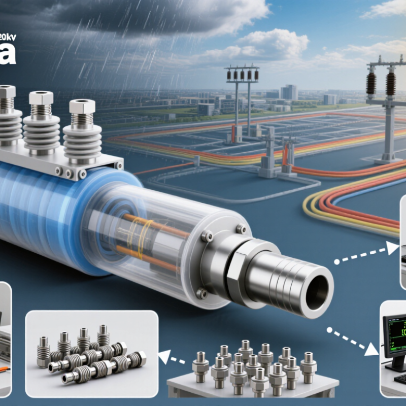
A 15kV 200A loadbreak junction supports flexible medium-voltage cable connections in compact distribution equipment. Its 200A rating defines continuous current capacity under specified installation and temperature conditions. It does not mean the junction can interrupt fault current.
The IEEE 386 interface is central to reliable field assembly. It controls key dimensions, mating surfaces, shielding, and electrical interchangeability for separable insulated connectors. A correctly matched interface helps prevent partial discharge, moisture entry, and uneven contact pressure. Installers should verify cable diameter, insulation thickness, elbow compatibility, and torque values before energizing. Small errors matter.
A 95kV BIL rating describes impulse withstand capability against short-duration surges. It is not the normal operating voltage. This distinction is sometimes overlooked during equipment selection. In practical inspections, clean interfaces, intact conductive shields, and properly fitted caps deserve close attention. The junction should also be checked against system grounding and insulation-coordination requirements. Manufacturing experience shows that dimensional control and dielectric testing must work together. I would not rely on a rating label alone; test records, material traceability, and routine inspection evidence provide stronger confidence. One gap remains common: field conditions rarely match laboratory conditions perfectly.
A China 15kV 200A loadbreak junction should be evaluated through its switching behavior, not only its label.
The 200A rating indicates continuous current capability under specified operating conditions. It does not automatically confirm reliable loadbreak performance in every installation.
A well-designed junction uses robust contacts, controlled arc interruption, and insulated interfaces. These details help operators disconnect energized circuits without unnecessary flashover risk.
Field engineers should check contact pressure, enclosure sealing, grounding provisions, and cable compatibility. Temperature-rise testing is also important, especially inside compact cabinets with limited ventilation.
A specification sheet may look convincing, yet installation errors can still reduce performance. That part is often underestimated.
A reliable 15kV 200A loadbreak junction begins with controlled material selection. Conductive parts usually use high-purity copper or aluminum with stable surface treatment. Insulating bodies require clean, moisture-resistant elastomer compounds. The compound must balance electrical strength, flexibility, and long-term sealing performance. Small material variations can affect interface pressure.
During molding, technicians monitor temperature, pressure, and curing time for every production batch. Precision molds shape the insulation and maintain consistent stress control layers. A clean production area matters because dust or trapped air can create weak points. Each molded part receives visual inspection, dimensional measurement, and batch identification. The process is repeatable, but never completely effortless.
Testing combines routine checks with sample-based verification. Manufacturers commonly inspect contact resistance, insulation integrity, dielectric withstand, and partial discharge performance. Mechanical checks confirm correct assembly force and loadbreak operation. Qualified laboratories may conduct thermal cycling, moisture exposure, and short-circuit-related evaluations under applicable industry requirements. Production records connect raw materials, operators, equipment settings, and test results. This traceability supports dependable field service. One molding defect can remain hidden without careful inspection, so quality teams should review failures rather than simply replace parts. That habit improves the next batch.
Evaluating a 15kV, 200A loadbreak junction starts with verified standards, not attractive photographs. Request the exact IEC and IEEE references used for design and testing. IEC 62271 requirements may address switching and insulation performance, while IEEE 386 can support separable connector evaluation. The applicable standard must match the product configuration.
Type-test evidence should identify voltage, current, frequency, test arrangement, and laboratory accreditation. Check dielectric withstand, partial discharge, temperature rise, short-time current, loadbreak operation, and mechanical endurance. A report is not enough. Confirm that the tested conductor size, interface, shielding system, and enclosure match the proposed junction. Small differences matter.
Ask how production units are controlled after qualification. Review incoming material checks, torque records, dimensional inspection, and routine electrical tests. Field experience is useful when supported by installation records, service conditions, and failure investigations. Speak with technical staff, not only sales contacts. Their answers should explain clearances, grounding paths, sealing, and cable preparation.
Be cautious with vague claims such as “IEC compliant.” Compliance depends on the specific clause, rating, and test method. I would also question unusually perfect data. Real projects include installation variation, cold weather, contamination, and human error. A reliable manufacturer discusses these limits openly and provides practical instructions. That honesty is sometimes more valuable than a polished certificate.
A 15kV 200A loadbreak junction supports controlled switching and dependable feeder connections in medium-voltage distribution systems. Typical applications include pad-mounted transformers, underground cable networks, sectionalizing points, and temporary maintenance arrangements. These junctions help crews isolate equipment without disturbing an entire feeder.
Installation quality strongly influences electrical performance. Confirm the voltage class, continuous current rating, interface type, and cable dimensions before work begins. The work area should remain clean, dry, and free from conductive dust. Cable insulation must be cut evenly, with the correct stripping length and smooth shielding transitions. Excessive bending can stress the connector body and cable termination. Follow the approved torque values precisely. Loose hardware creates heating. Over-tightening can damage interfaces.
Field conditions are rarely perfect. Experienced crews inspect contact surfaces, grounding paths, sealing points, and phase clearances before energizing. A second inspection often catches small errors. Service-life evaluation should include contact resistance, temperature rise, insulation resistance, and visible signs of tracking or corrosion. Recording these values during commissioning creates a useful baseline. Later comparisons can reveal gradual deterioration before failure occurs. Thermal cycling, moisture exposure, switching frequency, and fault history also affect expected service life. Some installations last for decades, but that assumption needs evidence. Periodic infrared inspections and documented maintenance provide stronger confidence than age alone.
This chart summarizes representative electrical reference values for a 15kV-class, 200A loadbreak junction used in medium-voltage distribution, transformer-primary connections, and feeder sectionalizing points. A 15kV-class system commonly uses a 15kV nominal rating with a maximum system voltage of approximately 15.5kV, while the continuous and loadbreak current ratings shown are 200A. Actual service life depends on switching frequency, fault exposure, connector condition, torque, moisture control, shielding integrity, and scheduled inspection.
Installation reference: verify phase-to-phase and phase-to-ground clearances, confirm grounding and shielding continuity, use the specified torque values, and inspect contact resistance and insulation condition during maintenance. Always confirm final ratings and service-life requirements against the applicable product standard and project specification.
„Thanks to the LUVIR technology, the solder resist process could be switched directly from the previously used mask exposure to direct exposure. As an outstanding digital solution on the market, this technology has been able to demonstrate fast process times and superior quality on our certified conventional ink in production. This allowed us to fully digitize the solder mask process at low cost – without process or ink adjustments. An excellent benefit to our production in Rot am See.“
Ralf Göhringer (Head of Production WE Rot am See)
I would definitely recommend the Limata machine and team for a future company purchase
Michael Greenaway
Compunetics Inc.
“The Limata ldi has been amazing!! Best thing we did was buy this machine”
Richard Brady
GM
Circuitlabs
“Since 2019, we have been running the Limata X1000 LDI system (including LUVIR for solder mask imaging) in daily production as an addition to our current process with film. The machine was capable of properly exposing Taiyo PSR-4000 BN (DI) solder mask types on normal to high-copper boards using a new and unique direct imaging process. The machine operating interface is very user friendly which allowed for a quick technical training curve. The pre-registration processing reduced several seconds of production time at every print. Limata support and service staff is incomparable. They supported our team every step of the way at basically any time of the day or night, with literally, an immediate response time, customizing the software interface to best fit our Operations and needs.
We have exposed more than 8,000 prints since end of October, on various solder mask colors and some resist film panels. Limata, has proven to be very capable and innovative. They are a strong contender in the industry.
We have very much enjoyed this project, and working with the team!
Thank you Limata for the continued support and being a part of our growth.”
Bill Sezate
Vice President, GM
Summit Interconnect
As a replacement to our current contact exposure process with film, the LIMATA X2000 system including LUVIR-Technology was capable of properly exposing non-LDI solder mask types using a direct imaging process. The machine offers cutting edge software with a very intuitive operating interface which allowed for quick technician training curve. The dual drawer system combined with pre-registration processing reduced several seconds of production time at every machine cycle. Limata support and service staff is world class. They added software patches to keep production running at shortest possible response times, customized the software interface to best fit our in-house Operations system, and even wrote a step-by-step machine processing manual. As a result of the project, we have exposed more than 16,000 times on various product types and solder mask brands/colors. Limata, in a very short timeframe as a company, has definitely shown they are truly innovative and will be challenging the industry of direct imaging for the top spot.
Kevin Beattie
Process Engineer
TTM Technologies
Forest Grove Division