Global buyers rarely choose a motor by catalog power alone. They examine torque, speed, mounting space, duty cycle, noise, and service access. A Gear Drive Motor must match the machine, not merely fit the quotation. In a conveyor room, a compact helical unit may run quietly. A worm gearbox may offer useful self-locking behavior. These differences affect energy use, heat, maintenance, and production continuity.
This guide introduces ten common gear drive motor types used across conveyors, mixers, packaging lines, lifts, automation equipment, and material-handling systems. It considers helical, bevel, worm, planetary, spur, and other practical configurations. Each type has a working context. Each also has limits. Planetary designs can deliver high torque in tight spaces, but their purchase and maintenance costs may be higher. Worm units are often economical, yet efficiency can fall under certain ratios and operating conditions.
Real purchasing decisions require more than technical labels. Engineers should verify rated torque, starting load, output shaft design, insulation class, ingress protection, voltage, frequency, and regional certification needs. Suppliers should provide test records, dimensional drawings, warranty terms, and replacement-part support. Small details matter. A misread duty rating can create expensive downtime. Even experienced buyers can overlook ambient temperature or frequent reversing. This overview cannot replace application testing. Some comparisons remain imperfect because installation and load behavior change performance. Still, it offers a reliable starting point for global buyers seeking safer, more efficient, and easier-to-maintain drive solutions.
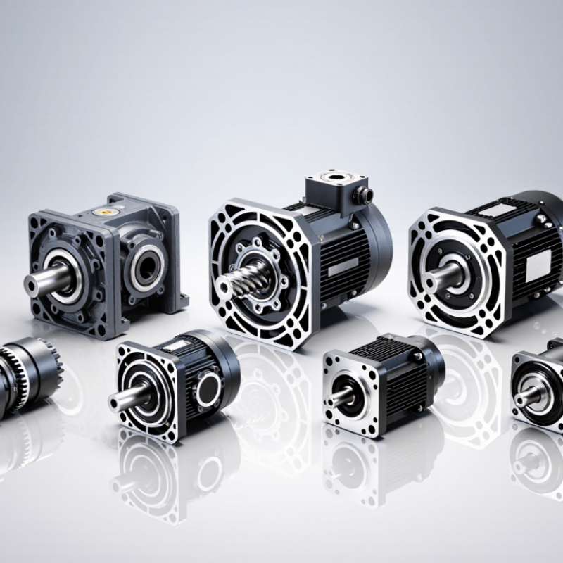
A gear drive motor combines an electric motor with a gearbox. The motor creates rotational energy at high speed. The gearbox reduces speed and increases usable torque. This exchange helps equipment move heavy loads with controlled force.
Inside the gearbox, gears transfer motion through meshing teeth. A small input gear turns a larger output gear. The ratio determines how much speed changes. Helical, spur, planetary, worm, and bevel arrangements suit different operating needs. For example, a conveyor may require steady torque, while a positioning table needs low backlash. Shaft alignment matters. Even slight misalignment can create noise, heat, and premature wear.
In workshop inspections, I look for oil stains, unusual vibration, and uneven tooth marks. These details often reveal problems before failure becomes obvious. Lubrication must match the gear material, temperature, and operating speed. Too little oil increases friction. Too much can also raise temperature.
Real systems are less tidy.
A motor’s rated torque does not guarantee reliable performance. Starting loads, stopping cycles, dust, moisture, and ambient heat can change the result. Engineers should compare continuous torque with peak torque and service-factor requirements. They should also check mounting position and shaft direction. One assumption deserves caution: a higher gear ratio is not always better. It may improve lifting force but reduce output speed and efficiency. In practical selection, the motor, gearbox, load, controller, and maintenance plan must work as one system.
A gear drive motor is classified by both its internal design and working environment. A practical top-ten list includes spur, helical, bevel, worm, planetary, cycloidal, parallel-shaft, right-angle, hollow-shaft, and washdown gear motors. The boundaries can overlap. That is normal.
Spur gear motors fit simple conveyors and low-cost machines. Helical designs deliver smoother, quieter torque for packaging lines. Bevel and right-angle units redirect power through 90 degrees, saving floor space. Worm drives provide high reduction in compact equipment, but their sliding contact can reduce efficiency. Planetary and cycloidal motors handle high torque and shock loads. Hollow-shaft models simplify mounting on rollers, while washdown designs support food-processing areas. Torque changes everything.
Application classification requires more than speed and power. The International Energy Agency reports that electric motor systems consume roughly half of global electricity. This makes efficiency a purchasing issue, not a technical footnote. U.S. Department of Energy motor-system guidance also highlights correct sizing, controls, and maintenance as major efficiency factors. A motor running far below its rated load may waste energy through poor system matching.
Global buyers should check duty cycle, ambient temperature, starting torque, noise, ingress protection, and service access. A worm motor may suit an occasional lift, but not continuous high-efficiency production. A planetary unit may be technically excellent, yet unnecessarily expensive for a light conveyor. I would not treat any ranking as universal. Real applications are messier than catalogs suggest.
How gear drive motors are classified by design and application
The chart compares representative reduction-ratio ranges commonly associated with major gear-drive designs. Actual performance depends on tooth geometry, staging, lubrication, load, motor speed, and the manufacturer’s specific configuration.
Top 10 Gear Drive Motor Types for Global Buyers
Gear drive motor selection starts with the load, speed, installation space, and operating environment. Spur gear motors suit simple, low-cost systems with moderate torque. Helical gear motors run more quietly and handle continuous duty well. Bevel gear motors transfer power through a right-angle layout. Worm gear motors provide high reduction ratios and useful self-locking behavior. However, efficiency may fall during long operating cycles. Noise matters.
Planetary gear motors deliver high torque from a compact housing. They work well in robotics, conveyors, and precision equipment. Cycloidal gear motors resist shock loads and offer strong positioning performance. Hypoid gear motors combine right-angle output with smoother contact than basic bevel designs. This difference can matter in dusty factories. Keep it practical.
Parallel-shaft gear motors fit narrow machines and maintain efficient power transmission. Hollow-shaft gear motors simplify mounting around driven shafts and reduce coupling parts. Rack-and-pinion gear motors support controlled linear movement in gates, lifts, and automation equipment. Buyers should check rated torque, service factor, duty cycle, voltage, insulation class, and local safety requirements. Stainless housings may help in washdown areas, but they can increase cost and weight. Space changes everything. A careful comparison should include spare-part access, delivery conditions, ambient temperature, and maintenance skill. I have seen efficient motors selected for loads they could not start reliably, so calculated starting torque deserves more attention.
Comparing gear drive motors starts with the working task, not the product label. Helical, worm, bevel, and planetary designs behave differently under load. Measure required torque at the output shaft. Include starting torque, shock loads, and a realistic service factor. A motor that looks powerful on paper may stall during conveyor starts.
Speed stability matters in packaging, mixers, and positioning equipment. Check rated speed, reduction ratio, and allowable speed variation. Efficiency also affects heat, electricity use, and operating cost. Worm drives can offer strong reduction in compact housings, but they may generate more heat. Temperature should be checked after several hours, not after ten quiet minutes.
Duty cycle reveals weaknesses quickly. Compare continuous, intermittent, and reversing operation. Inspect the stated thermal limits and the motor’s protection rating for dust or moisture. Noise and vibration measurements can expose poor alignment or worn bearings. Backlash is critical for lifting and indexing systems. Small errors become visible at the machine’s end.
Installation details deserve equal attention. Verify shaft diameter, mounting position, lubrication method, and available service space. I have seen suitable motors fail because an enclosure blocked cooling airflow. That mistake was preventable. A spreadsheet can also mislead when efficiency is measured under ideal conditions. Request test conditions, tolerances, and maintenance intervals. Independent certificates and traceable test records improve purchasing confidence, although paperwork never replaces a real load test.
Selecting a gear drive motor for a global market starts with the load, not the catalog label. Record continuous torque, peak torque, output speed, duty cycle, and starting frequency. A small conveyor may need a helical motor for quiet, efficient operation. A compact mixer may favor a planetary design for high torque density. Worm motors save space and often cost less, but heat and lower efficiency can hurt in continuous service. Check the heat.
Market conditions can change the correct choice. Humid coastal areas require sealed housings, corrosion-resistant finishes, and verified ingress protection. Dusty factories need effective sealing and a serviceable cooling path. Food-processing markets require cleanable surfaces and suitable materials. Voltage, frequency, mounting position, brake requirements, and local certification must match the installation site. A bevel gear motor suits right-angle layouts, while a shaft-mounted unit can simplify conveyor retrofits. Check spare-part access before approval. A perfect motor is useless if seals arrive six weeks late.
Compare total operating cost, not only purchase price. Calculate energy use, lubricant changes, service life, noise limits, and technician skill. Request efficiency data across your actual load range. Do not trust one peak-efficiency number. A recurring failure in equipment evaluations comes from ignoring jam conditions. The selection looked correct on paper. Leave a sensible service factor, but avoid blind oversizing. Excess capacity can increase cost, inrush current, and low-load losses. Pilot-test one unit with temperature, vibration, and noise readings before wider deployment.
| No. | Gear Drive Motor Type | Typical Reduction Ratio | Typical Output Speed | Typical Output Torque | Approximate Efficiency | Main Advantages | Typical Applications | Best Market Selection Criteria |
|---|---|---|---|---|---|---|---|---|
| 1 | Helical Gear Motor | 3:1–200:1 | 8–500 rpm | 10–20,000 N·m | 90–97% | High efficiency, quiet operation, good load capacity, and compact inline construction. | Conveyors, packaging equipment, material-handling systems, pumps, and process machinery. | A strong general-purpose choice where efficiency, continuous duty, and moderate-to-high torque are important. |
| 2 | Helical-Bevel Gear Motor | 5:1–300:1 | 5–350 rpm | 50–50,000 N·m | 90–96% | Efficient right-angle power transmission, high torque density, and flexible mounting positions. | Conveyors, mixers, industrial drives, food-processing machinery, and automated production lines. | Suitable for markets requiring right-angle output, energy efficiency, and robust continuous operation. |
| 3 | Worm Gear Motor | 5:1–100:1 | 10–300 rpm | 5–5,000 N·m | 50–90% | Low cost, compact right-angle design, quiet running, and high single-stage reduction capability. | Gates, small conveyors, lifts, packaging machines, rotary tables, and light-duty positioning systems. | Best where purchase cost, compactness, and low-to-moderate duty are prioritized over maximum efficiency. |
| 4 | Planetary Gear Motor | 3:1–100:1 per stage | 10–1,000 rpm | 20–100,000 N·m | 94–98% | Very high torque density, excellent load sharing, low backlash options, and compact dimensions. | Robotics, servo systems, machine tools, mobile equipment, wind-energy systems, and high-performance automation. | A preferred solution for compact, high-torque applications with strict precision and power-to-weight requirements. |
| 5 | Cycloidal Gear Motor | 6:1–119:1 per stage | 5–300 rpm | 100–50,000 N·m | 85–95% | High shock-load resistance, low backlash, long service life, and strong overload capability. | Robotic joints, indexing equipment, agitators, conveyors, machine tools, and heavy-duty automation. | Recommended for markets where impact loads, frequent starts and stops, and positioning accuracy are significant concerns. |
| 6 | Parallel-Shaft Helical Gear Motor | 3:1–200:1 | 8–500 rpm | 30–25,000 N·m | 93–97% | Short axial length, efficient power transmission, and convenient installation beside the driven machine. | Conveyor systems, belt drives, elevators, warehouse equipment, and material-handling machinery. | Useful where installation space is limited in the axial direction and high continuous-duty efficiency is needed. |
| 7 | Shaft-Mounted Helical Gear Motor | 5:1–70:1 | 20–350 rpm | 500–40,000 N·m | 93–97% | Direct mounting on the driven shaft, reduced foundation requirements, and simplified conveyor installation. | Bulk-material conveyors, crushers, feeders, mixers, and aggregate-handling equipment. | A practical choice for heavy industrial markets that value easy installation, compact layouts, and service accessibility. |
| 8 | Bevel Gear Motor | 2:1–200:1 | 10–750 rpm | 20–30,000 N·m | 90–96% | Efficient right-angle transmission, durable gear geometry, and suitability for high radial and axial loads. | Industrial conveyors, cranes, hoists, agricultural machinery, and power-transmission systems. | Appropriate for applications needing a right-angle drive with higher efficiency than many worm-drive alternatives. |
| 9 | Hypoid Gear Motor | 5:1–20:1 | 50–500 rpm | 10–2,000 N·m | 85–95% | Quiet right-angle operation, smooth torque transmission, and an offset output shaft that can support compact layouts. | Automated equipment, small conveyors, vehicle systems, access machinery, and compact industrial drives. | Well suited to markets seeking low noise, compact right-angle gearing, and moderate torque in space-constrained equipment. |
| 10 | Spur Gear Motor | 2:1–20:1 per stage | 50–1,500 rpm | 0.1–500 N·m | 90–98% | Simple construction, economical production, high efficiency at moderate ratios, and easy maintenance. | Small conveyors, office equipment, vending machines, actuators, medical devices, and light automation. | A cost-effective option for low- to medium-torque equipment where noise and high reduction ratios are not dominant requirements. |
| Note: The speed, torque, ratio, and efficiency figures are typical engineering ranges for comparison only. Actual performance depends on motor power, gear materials, service factor, duty cycle, lubrication, ambient conditions, mounting position, and manufacturer design. | ||||||||
„Thanks to the LUVIR technology, the solder resist process could be switched directly from the previously used mask exposure to direct exposure. As an outstanding digital solution on the market, this technology has been able to demonstrate fast process times and superior quality on our certified conventional ink in production. This allowed us to fully digitize the solder mask process at low cost – without process or ink adjustments. An excellent benefit to our production in Rot am See.“
Ralf Göhringer (Head of Production WE Rot am See)
I would definitely recommend the Limata machine and team for a future company purchase
Michael Greenaway
Compunetics Inc.
“The Limata ldi has been amazing!! Best thing we did was buy this machine”
Richard Brady
GM
Circuitlabs
“Since 2019, we have been running the Limata X1000 LDI system (including LUVIR for solder mask imaging) in daily production as an addition to our current process with film. The machine was capable of properly exposing Taiyo PSR-4000 BN (DI) solder mask types on normal to high-copper boards using a new and unique direct imaging process. The machine operating interface is very user friendly which allowed for a quick technical training curve. The pre-registration processing reduced several seconds of production time at every print. Limata support and service staff is incomparable. They supported our team every step of the way at basically any time of the day or night, with literally, an immediate response time, customizing the software interface to best fit our Operations and needs.
We have exposed more than 8,000 prints since end of October, on various solder mask colors and some resist film panels. Limata, has proven to be very capable and innovative. They are a strong contender in the industry.
We have very much enjoyed this project, and working with the team!
Thank you Limata for the continued support and being a part of our growth.”
Bill Sezate
Vice President, GM
Summit Interconnect
As a replacement to our current contact exposure process with film, the LIMATA X2000 system including LUVIR-Technology was capable of properly exposing non-LDI solder mask types using a direct imaging process. The machine offers cutting edge software with a very intuitive operating interface which allowed for quick technician training curve. The dual drawer system combined with pre-registration processing reduced several seconds of production time at every machine cycle. Limata support and service staff is world class. They added software patches to keep production running at shortest possible response times, customized the software interface to best fit our in-house Operations system, and even wrote a step-by-step machine processing manual. As a result of the project, we have exposed more than 16,000 times on various product types and solder mask brands/colors. Limata, in a very short timeframe as a company, has definitely shown they are truly innovative and will be challenging the industry of direct imaging for the top spot.
Kevin Beattie
Process Engineer
TTM Technologies
Forest Grove Division