Tps Sensors are small but essential components in modern engine management systems. They monitor the throttle plate’s position and report its movement to the engine control unit. This signal helps regulate fuel delivery, ignition timing, idle control, and sometimes automatic transmission behavior. When you press the accelerator, the sensor helps the vehicle understand how quickly and how far the throttle is opening.
Most Tps Sensors use either a resistive track with a moving contact or a contactless Hall-effect design. A typical sensor sends a changing voltage, often from roughly 0.5 volts at closed throttle to about 4.5 volts when fully open. The exact range varies by vehicle. A scan tool can display this movement in real time, while a multimeter may reveal dead spots or unstable readings. Small details matter, including connector corrosion, damaged wiring, and incorrect sensor alignment.
A faulty sensor may cause hesitation, rough idling, poor shifting, or an illuminated check-engine light. These signs are useful, but they are not conclusive. Another component may create similar symptoms. That is where careful testing becomes important. Follow the manufacturer’s service information, compare live data with measured voltage, and avoid replacing parts based only on guesswork. A simple test can mislead. Real diagnosis requires context, repeatable measurements, and attention to how the vehicle behaves on the road. Understanding how Tps Sensors work makes troubleshooting more logical, safer, and less expensive.
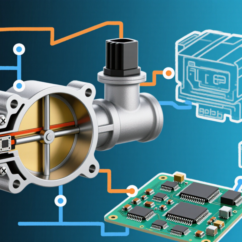
A throttle position sensor (TPS) reports throttle plate angle as an electrical signal to the engine control unit. In many systems, a potentiometer or Hall-effect sensor produces a changing voltage as the plate moves. A typical signal may sit near 0.5 V at closed throttle and approach 4.5 V when fully open. With the ignition on, a technician can monitor the voltage while moving the throttle slowly. The exact readings depend on sensor design and vehicle calibration. Small changes matter.
A smooth voltage sweep suggests the sensor is tracking movement consistently. A digital multimeter can show the changing signal; an oscilloscope may reveal brief dropouts that a meter misses. A sudden dip or jump can point to a worn track, loose connection, or wiring fault, though the reading alone does not prove which one. Not every setup matches. The 0.5–4.5 V range is a useful reference, not a universal specification. Checking service data and comparing the signal at several throttle positions helps avoid replacing a sensor based on one measurement.
What Are TPS Sensors and How Do They Work?
A throttle position sensor, or TPS, measures throttle-angle movement. Most systems use a 5 V reference circuit from the control unit. A potentiometric TPS moves a wiper across a resistive track. Its output changes smoothly, often from about 0.5 V at closed throttle to 4.5 V at wide opening. This voltage helps the controller adjust airflow, fuel delivery, and transmission response.
Hall-effect designs work differently. A small magnet rotates near a Hall element, changing its electrical signal without physical contact. This reduces wear and contamination risks. Many systems provide two output channels, often with opposite or proportional voltage patterns. The controller compares both signals for plausibility. The 2024 International Energy Agency Global EV Outlook reported more than 17 million electric cars sold worldwide in 2023. Even with electrification, position sensing remains important in pedals, valves, and thermal systems. The application is changing, not disappearing.
Tips: Check the 5 V reference before replacing a sensor. A weak ground can imitate sensor failure. Use an oscilloscope when possible. Watch for a smooth voltage sweep, not sudden drops. I have seen technicians trust a single multimeter reading too quickly. That approach is convenient, but incomplete. Industry sensor market analyses published in 2024 also show growing demand for non-contact sensing, although forecasts vary by region and definition. Calibration details still depend on the vehicle design.
| Comparison Dimension | Potentiometric TPS | Hall-Effect TPS |
|---|---|---|
| Sensing principle | A movable wiper slides along a resistive track as the throttle shaft turns, changing the signal voltage. | A magnetic field moves with the throttle shaft; a Hall-effect element detects the field and electronics produce an output signal. |
| Typical connections | Usually three: 5 V reference, sensor ground, and signal. | Usually power, sensor ground, and one or more signal wires. Some designs use additional signal circuits for redundancy. |
| How a 5 V reference circuit is used | The reference and ground are applied across the resistive track. The wiper provides a position-dependent voltage to the control module. | Many designs use a regulated supply near 5 V, but the required supply depends on the sensor. The output may be ratiometric or internally conditioned; check the circuit specification. |
| Signal behavior | Signal voltage generally changes smoothly with throttle angle. The direction and usable voltage range depend on the application. | The output may be an analog voltage or, in some designs, a digital signal. Output direction and range are application-specific. |
| Contact and wear | The wiper contacts the track, so wear, contamination, or vibration can cause an intermittent or noisy signal over time. | Position is sensed without a sliding electrical contact, reducing wear at the sensing element. It still depends on sound wiring, electronics, and magnetic components. |
| Common design features | May use one track or multiple tracks. Multiple tracks can provide independent position signals for plausibility checks. | May provide redundant outputs with different slopes or ranges so the control module can compare them. |
| Typical checks | Check the reference and ground, then observe the signal while slowly moving the throttle. Look for smooth change without dropouts, using the specified test procedure. | Check supply, ground, and signal(s) against the sensor specification. Confirm that redundant outputs maintain their specified relationship throughout movement. |
| Important diagnostic note | Voltage ranges, pin assignments, output direction, and acceptable signal relationships vary by application. Use the correct wiring diagram and service specifications; do not assume every TPS uses the same 5 V circuit or voltage limits. | |
A throttle position sensor, or TPS, reports the throttle plate’s angle to the engine control unit. It usually connects directly to the throttle shaft. Inside, a rotating contact moves across a resistive track. A steady reference voltage powers the sensor, while a ground completes the circuit. The remaining signal wire carries the changing output.
The operating sequence is straightforward. With the plate nearly closed, the signal may sit near 0.5 volts. As the driver presses the accelerator, the shaft turns and the contact moves along the track. The output voltage rises smoothly, often toward 4.5 volts at wide opening. The ECU reads this signal many times per second through an analog-to-digital converter. It then adjusts fuel delivery, ignition timing, idle control, and transmission response.
Real sensors are not perfectly smooth. A worn track can create a brief voltage drop or a noisy reading. That small fault may cause hesitation, unstable idle, or an unexpected warning light. During diagnosis, a technician should check the reference voltage, ground quality, and signal movement with a meter or scan tool. Move the throttle slowly. Watch for gaps. My first assumption was that a fixed voltage proved sensor health, but movement matters more than one reading. Exact voltage limits vary by system, so service data remains essential.
A throttle position sensor, or TPS, reports throttle angle to the engine control unit. In many systems, it uses a five-volt reference, ground, and a signal wire. At closed throttle, the signal often measures about 0.5 V. At full opening, it commonly rises near 4.5 V. The control unit reads this changing voltage as driver demand. It then adjusts fuel delivery, ignition timing, transmission response, and idle control.
The key detail is the signal’s smooth movement. With the ignition on and the engine stopped, a technician can back-probe the signal wire safely and monitor voltage. Open the throttle slowly. The reading should increase steadily, without sudden drops or jumps. A dead spot near light throttle can cause hesitation, unstable idle, or delayed shifting.
The 0.5 V and 4.5 V values are useful references, not universal laws. Some sensors use different limits, and a small offset may be acceptable. Always compare measurements with the vehicle’s service data. A reading of 0.6 V may be harmless, while a noisy 1.2 V signal can be a serious fault. Wiring damage, poor grounding, or connector corrosion can imitate a failed sensor. I have found this easy to overlook during diagnosis. The sensor gets blamed too quickly. A second voltage check often changes the picture.
A throttle position sensor (TPS) reports the throttle plate angle to the engine control module. Many electronic throttle systems use two signal tracks for safety. One voltage rises as the throttle opens, while the other changes at a different rate. The module compares both signals continuously.
Redundancy matters. Plausibility checks compare TPS readings with accelerator position, engine speed, airflow, and operating conditions. At closed throttle, the values should remain stable and believable. During a slow pedal movement, both signals should change smoothly, without sudden gaps or spikes. Watch the mismatch. A worn sensor may pass a basic voltage test but fail during movement. Wiring damage can create similar symptoms, especially near connectors exposed to heat and vibration.
OBD-II monitoring looks for signal disagreement, range errors, and unexpected changes. The control module may record a fault code and freeze-frame data when limits are exceeded. A scan tool can reveal live sensor percentages more clearly than a simple multimeter. Move the pedal slowly. Look for dropouts. Compare the readings with engine speed and airflow. Do not condemn the sensor immediately; poor grounds, loose terminals, and harness tension can imitate sensor failure. In practical diagnosis, one failed check can mislead me, so repeating the test under warm and cold conditions is worthwhile. The procedure is not perfect, but careful comparison often exposes the real fault.
„Thanks to the LUVIR technology, the solder resist process could be switched directly from the previously used mask exposure to direct exposure. As an outstanding digital solution on the market, this technology has been able to demonstrate fast process times and superior quality on our certified conventional ink in production. This allowed us to fully digitize the solder mask process at low cost – without process or ink adjustments. An excellent benefit to our production in Rot am See.“
Ralf Göhringer (Head of Production WE Rot am See)
I would definitely recommend the Limata machine and team for a future company purchase
Michael Greenaway
Compunetics Inc.
“The Limata ldi has been amazing!! Best thing we did was buy this machine”
Richard Brady
GM
Circuitlabs
“Since 2019, we have been running the Limata X1000 LDI system (including LUVIR for solder mask imaging) in daily production as an addition to our current process with film. The machine was capable of properly exposing Taiyo PSR-4000 BN (DI) solder mask types on normal to high-copper boards using a new and unique direct imaging process. The machine operating interface is very user friendly which allowed for a quick technical training curve. The pre-registration processing reduced several seconds of production time at every print. Limata support and service staff is incomparable. They supported our team every step of the way at basically any time of the day or night, with literally, an immediate response time, customizing the software interface to best fit our Operations and needs.
We have exposed more than 8,000 prints since end of October, on various solder mask colors and some resist film panels. Limata, has proven to be very capable and innovative. They are a strong contender in the industry.
We have very much enjoyed this project, and working with the team!
Thank you Limata for the continued support and being a part of our growth.”
Bill Sezate
Vice President, GM
Summit Interconnect
As a replacement to our current contact exposure process with film, the LIMATA X2000 system including LUVIR-Technology was capable of properly exposing non-LDI solder mask types using a direct imaging process. The machine offers cutting edge software with a very intuitive operating interface which allowed for quick technician training curve. The dual drawer system combined with pre-registration processing reduced several seconds of production time at every machine cycle. Limata support and service staff is world class. They added software patches to keep production running at shortest possible response times, customized the software interface to best fit our in-house Operations system, and even wrote a step-by-step machine processing manual. As a result of the project, we have exposed more than 16,000 times on various product types and solder mask brands/colors. Limata, in a very short timeframe as a company, has definitely shown they are truly innovative and will be challenging the industry of direct imaging for the top spot.
Kevin Beattie
Process Engineer
TTM Technologies
Forest Grove Division